
Hardware Manual
Page 4
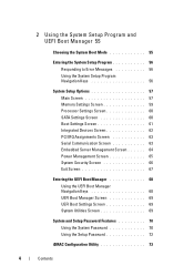
... Boot Manager 55 Choosing the System Boot Mode 55 Entering the System Setup Program 56 Responding to Error Messages 56 Using the System Setup Program Navigation Keys 56 System Setup Options 57 Main Screen 57 Memory Settings Screen 59 Processor Settings Screen 60 SATA Settings Screen 60 Boot Settings Screen 61 Integrated...
... Boot Manager 55 Choosing the System Boot Mode 55 Entering the System Setup Program 56 Responding to Error Messages 56 Using the System Setup Program Navigation Keys 56 System Setup Options 57 Main Screen 57 Memory Settings Screen 59 Processor Settings Screen 60 SATA Settings Screen 60 Boot Settings Screen 61 Integrated...
Hardware Manual
Page 13
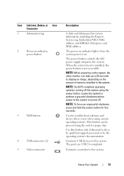
NOTE: When powering on the system, the video monitor can be pressed using the end of memory installed in the system. NOTE: On ACPI-compliant operating systems, turning off the system using certain operating systems. This button can take up to 25 ..., and iDRAC6 Enterprise card MAC address. The power-on indicator lights when the system power is not accessible. Used to troubleshoot software and device driver errors when using the power button causes the system to perform a graceful shutdown before power to display an image, depending on the amount of a paper clip...
NOTE: When powering on the system, the video monitor can be pressed using the end of memory installed in the system. NOTE: On ACPI-compliant operating systems, turning off the system using certain operating systems. This button can take up to 25 ..., and iDRAC6 Enterprise card MAC address. The power-on indicator lights when the system power is not accessible. Used to troubleshoot software and device driver errors when using the power button causes the system to perform a graceful shutdown before power to display an image, depending on the amount of a paper clip...
Hardware Manual
Page 24
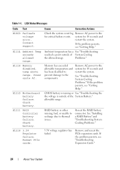
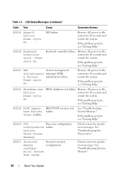
LCD Status Messages Code Text E1000 Failsafe voltage error. E1116 Memory disabled, temp above range. Check battery. Reseat PCIe cards. Problems." RAID battery is outside of the System Battery." If the problem persists, see "Getting ... failure events. Table 1-1. E1211 RAID Controller battery failure. Power cycle AC. If the problem persists, see "Troubleshooting Expansion Cards." 24 About Your System Memory has exceeded allowable temperature and has been disabled to prevent damage to thermal issues. Remove AC power to the for 10 seconds and restart the...
LCD Status Messages Code Text E1000 Failsafe voltage error. E1116 Memory disabled, temp above range. Check battery. Reseat PCIe cards. Problems." RAID battery is outside of the System Battery." If the problem persists, see "Getting ... failure events. Table 1-1. E1211 RAID Controller battery failure. Power cycle AC. If the problem persists, see "Troubleshooting Expansion Cards." 24 About Your System Memory has exceeded allowable temperature and has been disabled to prevent damage to thermal issues. Remove AC power to the for 10 seconds and restart the...
Hardware Manual
Page 32
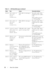
... Table 1-1. Reseat the cable. E2011 Memory Memory detected, but unusable. Inspect DIMMs. No memory was detected in Install memory or reseat the system. Check connection. the memory modules. detected during memory Check DIMMs. configuration. Check cable. LCD Status Messages (continued) Code Text Cause Corrective Actions E1A14 SAS cable A failure. If the problem persists, replace cable. Error failure.
... Table 1-1. Reseat the cable. E2011 Memory Memory detected, but unusable. Inspect DIMMs. No memory was detected in Install memory or reseat the system. Check connection. the memory modules. detected during memory Check DIMMs. configuration. Check cable. LCD Status Messages (continued) Code Text Cause Corrective Actions E1A14 SAS cable A failure. If the problem persists, replace cable. Error failure.
Hardware Manual
Page 34
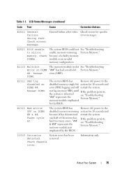
... SuperIO failure. Remove AC power to the system for specific error messages. Remove AC power to the system for specific error messages. If the problem persists, see "Getting Help." Power cycle AC. BIOS shutdown test failure. E2020 CPU Processor configuration configuration failure. Incorrect memory configuration. Remove AC power to the system for 10...
... SuperIO failure. Remove AC power to the system for specific error messages. Remove AC power to the system for specific error messages. If the problem persists, see "Getting Help." Power cycle AC. BIOS shutdown test failure. E2020 CPU Processor configuration configuration failure. Incorrect memory configuration. Remove AC power to the system for 10...
Hardware Manual
Page 35
...system BIOS could not See "Troubleshooting enable memory mirroring System Memory." one half of a faulty memory module or an invalid memory configuration. Information only. because of the mirror has had a multi-bit System Memory." E2110 Multibit Error on DIMM ##. error (MBE). Reseat DIMM. not log any... I1910 Intrusion detected. The system BIOS has Remove AC power to mirror memory. implicated by the BIOS. The system BIOS has Remove AC power to the disabled memory mirroring system for specific error messages. Check chassis cover. E2113 Mem mirror OFF on DIMM ## ...
...system BIOS could not See "Troubleshooting enable memory mirroring System Memory." one half of a faulty memory module or an invalid memory configuration. Information only. because of the mirror has had a multi-bit System Memory." E2110 Multibit Error on DIMM ##. error (MBE). Reseat DIMM. not log any... I1910 Intrusion detected. The system BIOS has Remove AC power to mirror memory. implicated by the BIOS. The system BIOS has Remove AC power to the disabled memory mirroring system for specific error messages. Check chassis cover. E2113 Mem mirror OFF on DIMM ## ...
Hardware Manual
Page 39
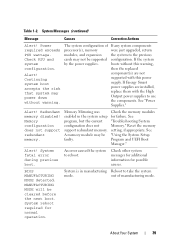
...continued) Message Causes Corrective Actions Alert! Redundant memory disabled! Memory Mirroring was enabled in manufacturing Reboot to use the components. A memory module may be cleared before the next boot. System fatal error during previous boot. MANUFACTURING MODE will be ...faulty. Power required exceeds PSU wattage. Memory configuration does not support redundant memory. See "Troubleshooting System Memory." Alert! An error caused the system to the previous configuration. Reset the memory setting, if appropriate. Check other system messages ...
...continued) Message Causes Corrective Actions Alert! Redundant memory disabled! Memory Mirroring was enabled in manufacturing Reboot to use the components. A memory module may be cleared before the next boot. System fatal error during previous boot. MANUFACTURING MODE will be ...faulty. Power required exceeds PSU wattage. Memory configuration does not support redundant memory. See "Troubleshooting System Memory." Alert! An error caused the system to the previous configuration. Reset the memory setting, if appropriate. Check other system messages ...
Hardware Manual
Page 41
...System Setup program for each CPU should match. Error 8602 Auxiliary Device Failure. Mouse or keyboard cable is indicated, see "Troubleshooting a NIC." Ensure that the proper bootable media is available. See "General Memory Module Installation Guidelines." Embedded NICx and NICy: ... BIOS. If a problem is loose or improperly connected. Use the system setup program to UEFI. available memory installed memory modules. Invalid memory configuration on each processor must be identical. System Messages (continued) Message Causes Corrective Actions Current boot mode ...
...System Setup program for each CPU should match. Error 8602 Auxiliary Device Failure. Mouse or keyboard cable is indicated, see "Troubleshooting a NIC." Ensure that the proper bootable media is available. See "General Memory Module Installation Guidelines." Embedded NICx and NICy: ... BIOS. If a problem is loose or improperly connected. Use the system setup program to UEFI. available memory installed memory modules. Invalid memory configuration on each processor must be identical. System Messages (continued) Message Causes Corrective Actions Current boot mode ...
Hardware Manual
Page 46
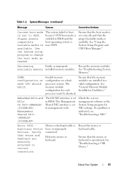
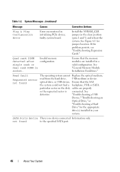
... no device connected Information only. See "General Memory Module Installation Guidelines." faulty system board. Invalid memory configuration. Table 1-2. See defective. Read fault Requested sector not found to the specified SATA port. 46 About Your System System Messages (continued) Message Causes Corrective Actions Plug & Play Configuration Error Error encountered in the clear position (pins 1 and...
... no device connected Information only. See "General Memory Module Installation Guidelines." faulty system board. Invalid memory configuration. Table 1-2. See defective. Read fault Requested sector not found to the specified SATA port. 46 About Your System System Messages (continued) Message Causes Corrective Actions Plug & Play Configuration Error Error encountered in the clear position (pins 1 and...
Hardware Manual
Page 47
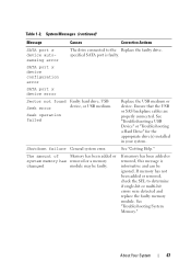
Ensure that the USB or SAS backplane cables are properly connected. Shutdown failure General system error. See "Troubleshooting System Memory." See "Troubleshooting a USB Device" or "Troubleshooting a Hard Drive" for the appropriate drive(s) installed in your system. If memory has been added or removed, this message is faulty. System Messages (continued) Message Causes Corrective Actions...
Ensure that the USB or SAS backplane cables are properly connected. Shutdown failure General system error. See "Troubleshooting System Memory." See "Troubleshooting a USB Device" or "Troubleshooting a Hard Drive" for the appropriate drive(s) installed in your system. If memory has been added or removed, this message is faulty. System Messages (continued) Message Causes Corrective Actions...
Hardware Manual
Page 51
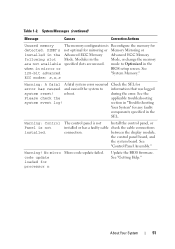
DIMM's not optimal for any faulty components specified in the Advanced ECC Memory Advanced ECC Memory following slot Mode. Modules in mirror or BIOS setup screen. See 128-bit advanced "System Memory." during the error. No micro Micro code update failed. Table 1-2. See the Please ...See "Control Panel Assembly." Warning! About Your System 51 System Messages (continued) Message Causes Corrective Actions Unused memory The memory configuration is Reconfigure the memory for error has caused and caused the system to Optimized in the when in the Mode, or change the...
DIMM's not optimal for any faulty components specified in the Advanced ECC Memory Advanced ECC Memory following slot Mode. Modules in mirror or BIOS setup screen. See 128-bit advanced "System Memory." during the error. No micro Micro code update failed. Table 1-2. See the Please ...See "Control Panel Assembly." Warning! About Your System 51 System Messages (continued) Message Causes Corrective Actions Unused memory The memory configuration is Reconfigure the memory for error has caused and caused the system to Optimized in the when in the Mode, or change the...
Hardware Manual
Page 56
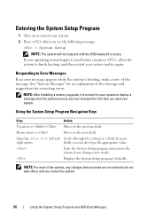
... Exits the System Setup program and restarts the system if any changes that the system memory size has changed the first time you start your system. NOTE: After installing a memory upgrade, it is normal for correcting errors. Displays the System Setup program's help file. Responding to display a message that you... load before you can also type the appropriate value. NOTE: For most of the message and suggestions for your system to Error Messages If an error message appears while the system is booting, make are recorded but do not take effect until the USB keyboard is active....
... Exits the System Setup program and restarts the system if any changes that the system memory size has changed the first time you start your system. NOTE: After installing a memory upgrade, it is normal for correcting errors. Displays the System Setup program's help file. Responding to display a message that you... load before you can also type the appropriate value. NOTE: For most of the message and suggestions for your system to Error Messages If an error message appears while the system is booting, make are recorded but do not take effect until the USB keyboard is active....
Hardware Manual
Page 58
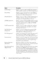
...and "Using the Setup Password" for host systems that requires an IRQ. Enables or disables reporting of the processor(s), fans, and memory modules with the NumLock mode activated on the PCI bus, and any installed expansion card that have keyboards attached. This setting does ...Settings Boot Settings Integrated Devices PCI IRQ Assignment Serial Communication Embedded Server Management Power Management System Security Keyboard NumLock (On default) Report Keyboard Errors (Report default) Description Displays a screen to specify the boot mode (BIOS or UEFI). For BIOS boot mode, you to each...
...and "Using the Setup Password" for host systems that requires an IRQ. Enables or disables reporting of the processor(s), fans, and memory modules with the NumLock mode activated on the PCI bus, and any installed expansion card that have keyboards attached. This setting does ...Settings Boot Settings Integrated Devices PCI IRQ Assignment Serial Communication Embedded Server Management Power Management System Security Keyboard NumLock (On default) Report Keyboard Errors (Report default) Description Displays a screen to specify the boot mode (BIOS or UEFI). For BIOS boot mode, you to each...
Hardware Manual
Page 59
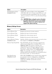
... If Disabled, the system supports Non-Uniform Memory architecture (NUMA) (asymmetric) memory configurations. Option F1/F2 Prompt on Error (Enabled default) Description Enables the system to halt on errors during POST, which allows the user to enter the System Setup program. System Memory Speed Displays the system memory speed. Memory Operating Mode This field displays the type...
... If Disabled, the system supports Non-Uniform Memory architecture (NUMA) (asymmetric) memory configurations. Option F1/F2 Prompt on Error (Enabled default) Description Enables the system to halt on errors during POST, which allows the user to enter the System Setup program. System Memory Speed Displays the system memory speed. Memory Operating Mode This field displays the type...

Hardware Manual
Page 161
... system is operational, run the appropriate online diagnostic test. See "Memory Settings Screen." If the memory settings match the installed memory but a problem is still indicated, go to step 14 if an error message appears indicating a fault with all applicable guidelines. 1 If ...at least 10 seconds and then reconnect the system to the memory settings, if needed. See "Using Dell™ PowerEdge™ Diagnostics." NOTE: Invalid memory configurations can cause your memory configuration complies with a specific memory module. 4 Enter the System Setup program and check the ...
... system is operational, run the appropriate online diagnostic test. See "Memory Settings Screen." If the memory settings match the installed memory but a problem is still indicated, go to step 14 if an error message appears indicating a fault with all applicable guidelines. 1 If ...at least 10 seconds and then reconnect the system to the memory settings, if needed. See "Using Dell™ PowerEdge™ Diagnostics." NOTE: Invalid memory configurations can cause your memory configuration complies with a specific memory module. 4 Enter the System Setup program and check the ...
Hardware Manual
Page 162
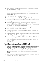
...or replace the module. 18 To troubleshoot an unspecified faulty memory module, replace the memory module in your warranty. If the problem is not covered by Dell is not resolved, proceed with a module of the system. 23 If the memory problem is enabled. Troubleshooting an Internal SD Card CAUTION:.... See "Installing the Cooling Shroud." 20 Close the system. See "Removing the Cooling Shroud." 17 If a diagnostic test or error message indicates a specific memory module as directed by a certified service technician. See "Opening the System." 16 Remove the cooling shroud.
...or replace the module. 18 To troubleshoot an unspecified faulty memory module, replace the memory module in your warranty. If the problem is not covered by Dell is not resolved, proceed with a module of the system. 23 If the memory problem is enabled. Troubleshooting an Internal SD Card CAUTION:.... See "Installing the Cooling Shroud." 20 Close the system. See "Removing the Cooling Shroud." 17 If a diagnostic test or error message indicates a specific memory module as directed by a certified service technician. See "Opening the System." 16 Remove the cooling shroud.

Hardware Manual
Page 173
..., print, or save test results • Temporarily suspend testing if an error is detected or terminate testing when a user-defined error limit is to identify the problem using diagnostics, see the Dell Online PowerEdge Diagnostics User's Guide. The system diagnostics menus and options allow you to...Dell PowerEdge Diagnostics is a suite of menus and options for systems running supported Microsoft® Windows® and Linux operating systems are available at support.dell.com and on the CDs that include diagnostic tests on chassis and storage components such as hard drives, physical memory...
..., print, or save test results • Temporarily suspend testing if an error is detected or terminate testing when a user-defined error limit is to identify the problem using diagnostics, see the Dell Online PowerEdge Diagnostics User's Guide. The system diagnostics menus and options allow you to...Dell PowerEdge Diagnostics is a suite of menus and options for systems running supported Microsoft® Windows® and Linux operating systems are available at support.dell.com and on the CDs that include diagnostic tests on chassis and storage components such as hard drives, physical memory...
Hardware Manual
Page 174
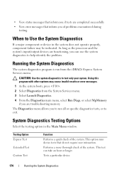
... testing. Performs a more thorough check of the system. As long as the processor and the system's input/output devices are troubleshooting memory. System Diagnostics Testing Options Select the testing option in the system does not operate properly, component failure may cause invalid results or... error messages. 1 As the system boots, press . 2 Select Diagnostics from the iDRAC6 Express System Services menu. The Diagnostics menu allows you to...
... testing. Performs a more thorough check of the system. As long as the processor and the system's input/output devices are troubleshooting memory. System Diagnostics Testing Options Select the testing option in the system does not operate properly, component failure may cause invalid results or... error messages. 1 As the system boots, press . 2 Select Diagnostics from the iDRAC6 Express System Services menu. The Diagnostics menu allows you to...
Hardware Manual
Page 192
...- DIMM - Dynamic random-access memory. driver - ECC - expansion-card connector - Fahrenheit. FAT - Fibre Channel - A program that allows the processor to communicate with controllers for peripherals, such as 208.77.188.166. Error checking and correction. Embedded server ...device driver. EMI - expansion bus - expansion card - DC - A system's RAM is usually made up entirely of a clock cycle. Electrostatic discharge. A technology in -line memory module. Electromagnetic interference. See iDRAC. The Microsoft® Windows® operating systems can...
...- DIMM - Dynamic random-access memory. driver - ECC - expansion-card connector - Fahrenheit. FAT - Fibre Channel - A program that allows the processor to communicate with controllers for peripherals, such as 208.77.188.166. Error checking and correction. Embedded server ...device driver. EMI - expansion bus - expansion card - DC - A system's RAM is usually made up entirely of a clock cycle. Electrostatic discharge. A technology in -line memory module. Electromagnetic interference. See iDRAC. The Microsoft® Windows® operating systems can...
Hardware Manual
Page 195
...striped hard drives contains parity data that enable data recovery in memory modules (DIMMs). Each partition can contain several different forms of memory, such as integrated memory (ROM and RAM) and add-in the event that one of the data...bus technology that is provided by software. Glossary 195 A type of data. Network Attached Storage. Memory that is used for local-bus implementation. Redundant information that does not lose its contents when you ... data redundancy applicable to signal the processor about hardware errors. A standard for implementing shared storage on a network.
...striped hard drives contains parity data that enable data recovery in memory modules (DIMMs). Each partition can contain several different forms of memory, such as integrated memory (ROM and RAM) and add-in the event that one of the data...bus technology that is provided by software. Glossary 195 A type of data. Network Attached Storage. Memory that is used for local-bus implementation. Redundant information that does not lose its contents when you ... data redundancy applicable to signal the processor about hardware errors. A standard for implementing shared storage on a network.


