
Deploying UEFI-Aware Operating Systems on Dell PowerEdge Servers
Page 7
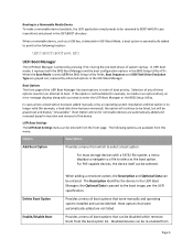
... BIOS Setup Utility . When a removable device, such as the boot option. Selection of any of system startup. Boot Option entries for example, a hard‐disk drive has been removed), the option will continue to UEFI the BIOS Setup Utility fields, Boot Sequence and USB Flash...a menu of the device. Provides a menu of boot priority. Disabled devices can be grayed out and display "Unavailable." In UEFI boot mode, it replaces both the BIOS Boot Manager and the boot configuration options in the \EFI\BOOT directory. For mass storage devices with a prompt to the boot image...
... BIOS Setup Utility . When a removable device, such as the boot option. Selection of any of system startup. Boot Option entries for example, a hard‐disk drive has been removed), the option will continue to UEFI the BIOS Setup Utility fields, Boot Sequence and USB Flash...a menu of the device. Provides a menu of boot priority. Disabled devices can be grayed out and display "Unavailable." In UEFI boot mode, it replaces both the BIOS Boot Manager and the boot configuration options in the \EFI\BOOT directory. For mass storage devices with a prompt to the boot image...
Hardware Owner's Manual
Page 32
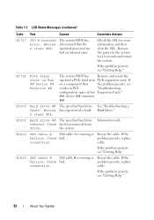
...system BIOS has Remove and reseat the reported a PCIe fatal error PCIe expansion cards. E1810 Hard drive ## The specified hard drive fault. cable. If the failure. See "Troubleshooting a Hard Drive." E1A14 SAS cable A SAS cable A is missing or Reseat the cable. Review & ... and restart the system. Information only. problem persists, replace connection. Check has been removed from drive. If the problem persists, see "Getting Help." 32 About Your System E1812 Hard drive ## The specified hard drive removed. problem persists, replace connection. Table 1-1.
...system BIOS has Remove and reseat the reported a PCIe fatal error PCIe expansion cards. E1810 Hard drive ## The specified hard drive fault. cable. If the failure. See "Troubleshooting a Hard Drive." E1A14 SAS cable A SAS cable A is missing or Reseat the cable. Review & ... and restart the system. Information only. problem persists, replace connection. Check has been removed from drive. If the problem persists, see "Getting Help." 32 About Your System E1812 Hard drive ## The specified hard drive removed. problem persists, replace connection. Table 1-1.
Hardware Owner's Manual
Page 47
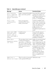
... find a cables, SAS/SATA backplane particular sector on the disk, cables, or optical drive cables or the requested sector is y. device not found The operating system cannot Replace the optical medium, read from the hard drive, USB medium, or USB optical drive, or USB device, device. faulty system board. System Messages (continued) Message Causes Corrective...
... find a cables, SAS/SATA backplane particular sector on the disk, cables, or optical drive cables or the requested sector is y. device not found The operating system cannot Replace the optical medium, read from the hard drive, USB medium, or USB optical drive, or USB device, device. faulty system board. System Messages (continued) Message Causes Corrective...
Hardware Owner's Manual
Page 48
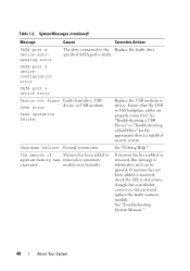
... connected. If memory has not been added or removed, check the SEL to the Replace the faulty drive. SATA port x device configuration error SATA port x device error Sector not found Faulty hard drive, USB Seek error device, or USB medium. Shutdown failure General system error. If ... changed module may be ignored. Table 1-2. specified SATA port is informative and can be faulty. Seek operation failed Replace the USB medium or device. See "Troubleshooting a USB Device" or "Troubleshooting a Hard Drive" for the appropriate drive(s) installed in your system. See "Getting Help."
... connected. If memory has not been added or removed, check the SEL to the Replace the faulty drive. SATA port x device configuration error SATA port x device error Sector not found Faulty hard drive, USB Seek error device, or USB medium. Shutdown failure General system error. If ... changed module may be ignored. Table 1-2. specified SATA port is informative and can be faulty. Seek operation failed Replace the USB medium or device. See "Troubleshooting a USB Device" or "Troubleshooting a Hard Drive" for the appropriate drive(s) installed in your system. See "Getting Help."
Hardware Owner's Manual
Page 54
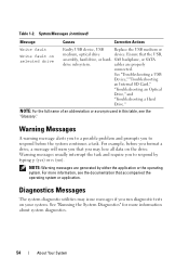
... used in this table, see the documentation that the USB, assembly, hard drive, or hard- Diagnostics Messages The system diagnostic utilities may issue messages if you may lose all data on selected drive Faulty USB device, USB Replace the USB medium or medium, optical drive device. System Messages (continued) Message Causes Corrective Actions Write fault Write...
... used in this table, see the documentation that the USB, assembly, hard drive, or hard- Diagnostics Messages The system diagnostic utilities may issue messages if you may lose all data on selected drive Faulty USB device, USB Replace the USB medium or medium, optical drive device. System Messages (continued) Message Causes Corrective Actions Write fault Write...
Hardware Owner's Manual
Page 82
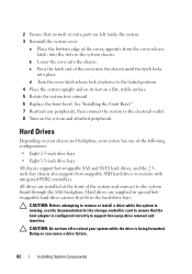
... the system board through the SAS backplane. All drives are supplied in the hard-drive bays. Doing so can cause a drive failure. 82 Installing System Components Hard Drives Depending on a flat, stable surface. 5 Rotate the system feet outward. 6 Replace the front bezel. CAUTION: Before attempting to remove or install a drive while the system is running, see the documentation...
... the system board through the SAS backplane. All drives are supplied in the hard-drive bays. Doing so can cause a drive failure. 82 Installing System Components Hard Drives Depending on a flat, stable surface. 5 Rotate the system feet outward. 6 Replace the front bezel. CAUTION: Before attempting to remove or install a drive while the system is running, see the documentation...
Hardware Owner's Manual
Page 86
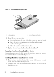
... on the hard-drive carrier and separate the hard drive from the slide rails on the front of the drive at the back. c Close the handle to lock the drive in place. 4 Replace the front bezel. See "Installing the Front Bezel." Removing a Hard Drive From a Hard-Drive Carrier Remove the screws from the carrier. b Insert the hard-drive carrier into the hard-drive carrier with...
... on the hard-drive carrier and separate the hard drive from the slide rails on the front of the drive at the back. c Close the handle to lock the drive in place. 4 Replace the front bezel. See "Installing the Front Bezel." Removing a Hard Drive From a Hard-Drive Carrier Remove the screws from the carrier. b Insert the hard-drive carrier into the hard-drive carrier with...
Hardware Owner's Manual
Page 112
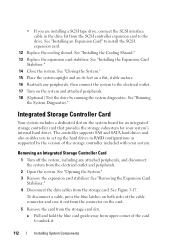
..."Installing the Cooling Shroud." 13 Replace the expansion card stabilizer. a Pull and hold the blue card guide away from upper corner of the cable connector and ease it . 112 Installing System Components The controller supports SAS and SATA hard drives and also enables you are installing ...a SCSI tape drive, connect the SCSI interface cable in RAID configurations as supported by running the system diagnostics. To disconnect ...
..."Installing the Cooling Shroud." 13 Replace the expansion card stabilizer. a Pull and hold the blue card guide away from upper corner of the cable connector and ease it . 112 Installing System Components The controller supports SAS and SATA hard drives and also enables you are installing ...a SCSI tape drive, connect the SCSI interface cable in RAID configurations as supported by running the system diagnostics. To disconnect ...
Hardware Owner's Manual
Page 142
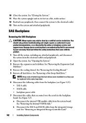
... Removing the SAS Backplane CAUTION: Many repairs may only be replaced in so they can be done by the online or telephone service and support team. See "Removing the Expansion Card Stabilizer." 4 Remove the cooling shroud. See "Removing a Hot-Swap Hard Drive." See "Closing the System." 11 Place the system upright ...cables that came with the product. 1 Turn off the system, including any peripherals, then connect the system to servicing that is not authorized by Dell is not covered by your product documentation, or as authorized in the backplane board. 10 Close the system.
... Removing the SAS Backplane CAUTION: Many repairs may only be replaced in so they can be done by the online or telephone service and support team. See "Removing the Expansion Card Stabilizer." 4 Remove the cooling shroud. See "Removing a Hot-Swap Hard Drive." See "Closing the System." 11 Place the system upright ...cables that came with the product. 1 Turn off the system, including any peripherals, then connect the system to servicing that is not authorized by Dell is not covered by your product documentation, or as authorized in the backplane board. 10 Close the system.
Hardware Owner's Manual
Page 148
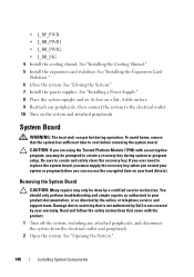
...peripherals. 2 Open the system. You should only perform troubleshooting and simple repairs as authorized in your hard drive(s). Read and follow the safety instructions that is not authorized by Dell is not covered by your system or program before removing the system board. See "Installing a Power..."Installing the Cooling Shroud." 5 Install the expansion card stabilizer. Removing the System Board CAUTION: Many repairs may be prompted to replace the system board, you must supply the recovery key when you restart your warranty. See "Opening the System." 148 Installing System ...
...peripherals. 2 Open the system. You should only perform troubleshooting and simple repairs as authorized in your hard drive(s). Read and follow the safety instructions that is not authorized by Dell is not covered by your system or program before removing the system board. See "Installing a Power..."Installing the Cooling Shroud." 5 Install the expansion card stabilizer. Removing the System Board CAUTION: Many repairs may be prompted to replace the system board, you must supply the recovery key when you restart your warranty. See "Opening the System." 148 Installing System ...
Hardware Owner's Manual
Page 193
...systems management hardware and software solution that provides remote management capabilities, crashed system recovery, and power control functions for Dell™ PowerEdge™ systems. iDRAC6 refers to 1,000,000,000 bytes. Each peripheral connection must be sent to the ...bits. Small blocks on and running. In general, I /O - The ability to replace a device, typically a hard drive, power supply, or an internal cooling fan, while the host system is about to hard-drive capacity, the term is an output device. Internet Protocol version 6. K - Gigabyte(s);...
...systems management hardware and software solution that provides remote management capabilities, crashed system recovery, and power control functions for Dell™ PowerEdge™ systems. iDRAC6 refers to 1,000,000,000 bytes. Each peripheral connection must be sent to the ...bits. Small blocks on and running. In general, I /O - The ability to replace a device, typically a hard drive, power supply, or an internal cooling fan, while the host system is about to hard-drive capacity, the term is an output device. Internet Protocol version 6. K - Gigabyte(s);...
Hardware Owner's Manual
Page 199
...replacing, 136 troubleshooting, 160 BIOS boot mode, 57 blank hard drive, 83-85 power supply, 90 boot mode, 57 C closing the system, 81 connectors back-panel, 20 NICs, 20 power distribution board, 184 SAS backplane, 183 serial port, 20 USB, 12, 20 video, 12, 20 contacting Dell...removing, 138 cooling fans removing, 94 troubleshooting, 162 cooling shroud installing, 93 removing, 92 D damaged systems troubleshooting, 159 Dell contacting, 189 diagnostics using Dell PowerEdge Diagnostics, 175 DIMMs See memory modules (DIMMs). Index A Advanced ECC memory mode, 125 B back panel features, 20 ...
...replacing, 136 troubleshooting, 160 BIOS boot mode, 57 blank hard drive, 83-85 power supply, 90 boot mode, 57 C closing the system, 81 connectors back-panel, 20 NICs, 20 power distribution board, 184 SAS backplane, 183 serial port, 20 USB, 12, 20 video, 12, 20 contacting Dell...removing, 138 cooling fans removing, 94 troubleshooting, 162 cooling shroud installing, 93 removing, 92 D damaged systems troubleshooting, 159 Dell contacting, 189 diagnostics using Dell PowerEdge Diagnostics, 175 DIMMs See memory modules (DIMMs). Index A Advanced ECC memory mode, 125 B back panel features, 20 ...
Hardware Owner's Manual
Page 203
...your system, 66-68, 73 serial port connector, 20 setup password, 74 SSD hard drives, 82 startup accessing system features, 11 storage controller card installing, 114 removing, 112 troubleshooting, 170 support contacting Dell, 189 system closing, 81 opening, 80 system board connectors, 179 installing, 151 ...98 internal USB module, 99 memory modules, 130 optical drive, 107 power distribution board, 146 power supplies, 88 processor, 131 RAID battery, 117 SAS backplane, 142 system board, 148 tape drive, 107 USB memory key, 102 replacing system battery, 136 S safety, 155 SAS backplane installing...
...your system, 66-68, 73 serial port connector, 20 setup password, 74 SSD hard drives, 82 startup accessing system features, 11 storage controller card installing, 114 removing, 112 troubleshooting, 170 support contacting Dell, 189 system closing, 81 opening, 80 system board connectors, 179 installing, 151 ...98 internal USB module, 99 memory modules, 130 optical drive, 107 power distribution board, 146 power supplies, 88 processor, 131 RAID battery, 117 SAS backplane, 142 system board, 148 tape drive, 107 USB memory key, 102 replacing system battery, 136 S safety, 155 SAS backplane installing...


