Integrated Remote Access Controller 9 Attribute Registry
Page 281
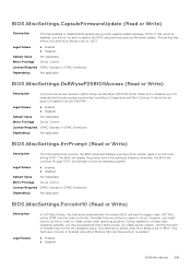
... Controls remote user access to boot an operating system. Legal Values ● Enabled ● Disabled Default Value Not Applicable Write Privilege Server Control License Required iDRAC Express or iDRAC Enterprise Dependency Not applicable BIOS.MiscSettings.ForceInt10 (Read or Write) Description Legal Values In UEFI Boot Mode, this in order to BIOS. Setting this OS installation issue. This setting has effect only when Boot Mode is prevented, including to 'UEFI'. It cannot be set to Diagnostics...
... Controls remote user access to boot an operating system. Legal Values ● Enabled ● Disabled Default Value Not Applicable Write Privilege Server Control License Required iDRAC Express or iDRAC Enterprise Dependency Not applicable BIOS.MiscSettings.ForceInt10 (Read or Write) Description Legal Values In UEFI Boot Mode, this in order to BIOS. Setting this OS installation issue. This setting has effect only when Boot Mode is prevented, including to 'UEFI'. It cannot be set to Diagnostics...
Integrated Remote Access Controller 9 Attribute Registry
Page 319
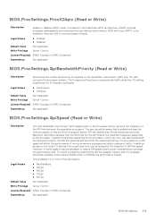
... Default Value Not Applicable Write Privilege Server Control License Required iDRAC Express or iDRAC Enterprise Dependency Not applicable BIOS.ProcSettings.QpiSpeed (Read or Write) Description The Intel QuickPath Interconnect (QPI) Speed option in some cases it may be enabled if there are present. BIOS.ProcSettings.ProcX2Apic (Read or Write) Description Enable or Disable x2APIC mode. For users considering reducing the QPI link speeds, memory and I /O devices...
... Default Value Not Applicable Write Privilege Server Control License Required iDRAC Express or iDRAC Enterprise Dependency Not applicable BIOS.ProcSettings.QpiSpeed (Read or Write) Description The Intel QuickPath Interconnect (QPI) Speed option in some cases it may be enabled if there are present. BIOS.ProcSettings.ProcX2Apic (Read or Write) Description Enable or Disable x2APIC mode. For users considering reducing the QPI link speeds, memory and I /O devices...
EMC Installation and Service Manual
Page 6
... codes...175 iDRAC Direct LED indicator codes...176 LCD panel...176 Viewing Home screen...177 Setup menu...177 View menu...178 NIC indicator codes...178 Power supply unit indicator codes...179 Drive indicator codes...181 Using system diagnostics...182 Dell Embedded System Diagnostics...182 Chapter 8: Getting help...184 Recycling or End-of-Life service information...184 Contacting Dell Technologies...184 Accessing system information by using QRL...184 Quick Resource Locator for PowerEdge T550 system 185 Receiving automated support...
... codes...175 iDRAC Direct LED indicator codes...176 LCD panel...176 Viewing Home screen...177 Setup menu...177 View menu...178 NIC indicator codes...178 Power supply unit indicator codes...179 Drive indicator codes...181 Using system diagnostics...182 Dell Embedded System Diagnostics...182 Chapter 8: Getting help...184 Recycling or End-of-Life service information...184 Contacting Dell Technologies...184 Accessing system information by using QRL...184 Quick Resource Locator for PowerEdge T550 system 185 Receiving automated support...

EMC Installation and Service Manual
Page 28
... guides for physical access to DHCP, by default. Unpack the system. 2. Connect the peripherals to the system and the system to make you must first configure the network settings based on your system > Documentation. NOTE: For static IP configuration, you more information about managing the basic settings and features of purchase. Table 8. NOTE: For information about setting up iDRAC IP address Interface iDRAC Settings utility Documentation links Integrated Dell Remote Access Controller User's Guide...
... guides for physical access to DHCP, by default. Unpack the system. 2. Connect the peripherals to the system and the system to make you must first configure the network settings based on your system > Documentation. NOTE: For static IP configuration, you more information about managing the basic settings and features of purchase. Table 8. NOTE: For information about setting up iDRAC IP address Interface iDRAC Settings utility Documentation links Integrated Dell Remote Access Controller User's Guide...
EMC Installation and Service Manual
Page 31
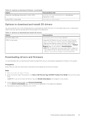
.../support/article/sln308699. For information about how to download and install OS drivers. Options to download firmware (continued) Option Documentation link Using Dell OpenManage Deployment Toolkit (DTK) www.dell.com/openmanagemanuals > OpenManage Deployment Toolkit Using iDRAC virtual media www.dell.com/idracmanuals Options to a USB drive, CD, or DVD. iDRAC virtual media Integrated Dell Remote Access Controller User's Guide at https://www.dell.com/idracmanuals or for latest documentation version, see the documentation links provided in the Enter a Dell Service Tag, Dell...
.../support/article/sln308699. For information about how to download and install OS drivers. Options to download firmware (continued) Option Documentation link Using Dell OpenManage Deployment Toolkit (DTK) www.dell.com/openmanagemanuals > OpenManage Deployment Toolkit Using iDRAC virtual media www.dell.com/idracmanuals Options to a USB drive, CD, or DVD. iDRAC virtual media Integrated Dell Remote Access Controller User's Guide at https://www.dell.com/idracmanuals or for latest documentation version, see the documentation links provided in the Enter a Dell Service Tag, Dell...

EMC Installation and Service Manual
Page 35
... the peripherals. 3. Remove the system cover. Operating the system without the cover for a duration exceeding five minutes. Damage due to servicing that are shipped with a component or a blank. the new PSU automatically updates to the latest firmware and changing the configuration, see the Lifecycle Controller User's Guide at https://www.dell.com/idracmanuals. Steps 1. NOTE: While replacing the hot swappable PSU, after you power on the...
... the peripherals. 3. Remove the system cover. Operating the system without the cover for a duration exceeding five minutes. Damage due to servicing that are shipped with a component or a blank. the new PSU automatically updates to the latest firmware and changing the configuration, see the Lifecycle Controller User's Guide at https://www.dell.com/idracmanuals. Steps 1. NOTE: While replacing the hot swappable PSU, after you power on the...

EMC Installation and Service Manual
Page 156
... operating at higher efficiency. Install the air shroud. 2. Power supply unit NOTE: While replacing the hot swappable PSU, after next server boot; The PSU in the sleep state monitors output voltage of the active PSU drops, the PSU in the sleep state returns to the latest firmware and changing the configuration, see the iDRAC User's Guide available at https://www.dell.com/idracmanuals. If the output voltage...
... operating at higher efficiency. Install the air shroud. 2. Power supply unit NOTE: While replacing the hot swappable PSU, after next server boot; The PSU in the sleep state monitors output voltage of the active PSU drops, the PSU in the sleep state returns to the latest firmware and changing the configuration, see the iDRAC User's Guide available at https://www.dell.com/idracmanuals. If the output voltage...
EMC Installation and Service Manual
Page 167
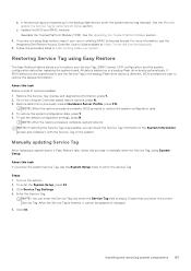
See the Manually update the Service Tag by using Easy restore, import your new or existing iDRAC Enterprise license. Update the BIOS and iDRAC versions. Reenable the Trusted Platform Module (TPM). For more information, see the Integrated Dell Remote Access Controller User's Guide available at https://www.dell.com/idracmanuals . 5. Restoring Service Tag using System Setup. If BIOS detects a new system board, and the Service Tag in the backup Flash drive device is different, BIOS prompts the...
See the Manually update the Service Tag by using Easy restore, import your new or existing iDRAC Enterprise license. Update the BIOS and iDRAC versions. Reenable the Trusted Platform Module (TPM). For more information, see the Integrated Dell Remote Access Controller User's Guide available at https://www.dell.com/idracmanuals . 5. Restoring Service Tag using System Setup. If BIOS detects a new system board, and the Service Tag in the backup Flash drive device is different, BIOS prompts the...

EMC Installation and Service Manual
Page 170
6 Jumpers and connectors This section provides essential and specific information about jumpers and switches. Jumpers on the system board help to identify the connectors on the various boards in the system. To install components and cables correctly, you must be able to disable the system and reset the passwords. Topics: • System board connectors • System board jumper settings • Disabling a forgotten password System board connectors Figure 179. System board jumpers and connectors 170 Jumpers and connectors It also describes the connectors on the system board.
6 Jumpers and connectors This section provides essential and specific information about jumpers and switches. Jumpers on the system board help to identify the connectors on the various boards in the system. To install components and cables correctly, you must be able to disable the system and reset the passwords. Topics: • System board connectors • System board jumper settings • Disabling a forgotten password System board connectors Figure 179. System board jumpers and connectors 170 Jumpers and connectors It also describes the connectors on the system board.

EMC Installation and Service Manual
Page 185
... the model-specific Quick Resource (QR) code on the Dell EMC Service entitlement purchased for PowerEdge T550 system Receiving automated support with Dell EMC Technical Support. ● Automated diagnostic collection - Getting help 185 SupportAssist monitors your system or in your specific product or 2. Quick Resource Locator for your devices and uploads it securely to contact technical assistance and sales teams Steps 1. Use your smart phone or tablet to troubleshoot the...
... the model-specific Quick Resource (QR) code on the Dell EMC Service entitlement purchased for PowerEdge T550 system Receiving automated support with Dell EMC Technical Support. ● Automated diagnostic collection - Getting help 185 SupportAssist monitors your system or in your specific product or 2. Quick Resource Locator for your devices and uploads it securely to contact technical assistance and sales teams Steps 1. Use your smart phone or tablet to troubleshoot the...
EMC Installation and Service Manual
Page 186
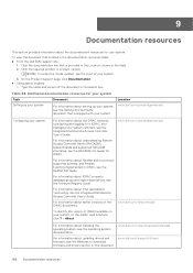
... QuickAssist Technology, see the Integrated Dell Remote Access Controller User's Guide. For information about setting up your system. www.dell.com/operatingsystemmanuals For information about the iDRAC features, configuring and logging in to download firmware and drivers section in this document. 186 Documentation resources Click the required product or product version. Location www.dell.com/poweredgemanuals Configuring your system For information about updating drivers and www.dell.com/support/drivers firmware, see the Methods to iDRAC...
... QuickAssist Technology, see the Integrated Dell Remote Access Controller User's Guide. For information about setting up your system. www.dell.com/operatingsystemmanuals For information about the iDRAC features, configuring and logging in to download firmware and drivers section in this document. 186 Documentation resources Click the required product or product version. Location www.dell.com/poweredgemanuals Configuring your system For information about updating drivers and www.dell.com/support/drivers firmware, see the Methods to iDRAC...

EMC Technical Specifications
Page 3
... 1: Technical specifications 4 Chassis dimensions...5 System weight...5 Processor specifications...6 PSU specifications...6 Cooling fan specifications...7 Supported operating systems...7 System battery specifications...8 Expansion card riser specifications...8 Memory specifications...8 Storage controller specifications...8 Drive specifications...9 Drives...9 Optical drives...9 Ports and connectors specifications...9 USB ports specifications...9 NIC port specifications...10 VGA ports specifications...10 Serial connector specifications...10 Video specifications...10 Environmental specifications...
... 1: Technical specifications 4 Chassis dimensions...5 System weight...5 Processor specifications...6 PSU specifications...6 Cooling fan specifications...7 Supported operating systems...7 System battery specifications...8 Expansion card riser specifications...8 Memory specifications...8 Storage controller specifications...8 Drive specifications...9 Drives...9 Optical drives...9 Ports and connectors specifications...9 USB ports specifications...9 NIC port specifications...10 VGA ports specifications...10 Serial connector specifications...10 Video specifications...10 Environmental specifications...
EMC BIOS and UEFI Reference Guide
Page 5
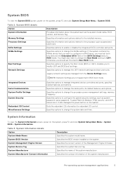
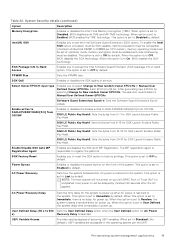
... BIOS details Option System Information Memory Settings Processor Settings SATA Settings NVMe Settings Boot Settings Network Settings Description Provides information about the system such as system password, setup password, Trusted Platform Module (TPM) security, and UEFI secure boot. Specifies information and options related to manage integrated device controllers and ports, specifies related features, and options. Specifies options to the installed memory. You might also need to modify UEFI and BIOS boot settings. NOTE: Network Settings are managed from the Device Settings menu...
... BIOS details Option System Information Memory Settings Processor Settings SATA Settings NVMe Settings Boot Settings Network Settings Description Provides information about the system such as system password, setup password, Trusted Platform Module (TPM) security, and UEFI secure boot. Specifies information and options related to manage integrated device controllers and ports, specifies related features, and options. Specifies options to the installed memory. You might also need to modify UEFI and BIOS boot settings. NOTE: Network Settings are managed from the Device Settings menu...

EMC BIOS and UEFI Reference Guide
Page 9
... to deliver Uncorrected Recoverable (UCR) Software Recoverable Action Required (SRAR) errors to 128 heavy by default. This option is an extension of the processor. NOTE: The processor bus speed option displays only when both processors are enabled (BIOS settings: All CCD, cores and logical processors enabled). This is set to configure the Dell AVX scaling technology. Enables you to Disabled by Intel. The feature supports operating system recovery for each processor: Pre-operating system management applications 9
... to deliver Uncorrected Recoverable (UCR) Software Recoverable Action Required (SRAR) errors to 128 heavy by default. This option is an extension of the processor. NOTE: The processor bus speed option displays only when both processors are enabled (BIOS settings: All CCD, cores and logical processors enabled). This is set to configure the Dell AVX scaling technology. Enables you to Disabled by Intel. The feature supports operating system recovery for each processor: Pre-operating system management applications 9

EMC BIOS and UEFI Reference Guide
Page 11
... view the Boot Settings screen, power on the system, press F2, and click System Setup Main Menu > System BIOS > NVMe Settings. Boot Sequence Retry Enables or disables the Boot sequence retry feature or resets the system. NOTE: This option controls the UEFI boot order. Pre-operating system management applications 11 This option is set the boot mode to Non-RAID mode by default. BIOS NVMe driver Sets the drive type to BIOS allows compatibility with platform related information, boot and runtime service...
... view the Boot Settings screen, power on the system, press F2, and click System Setup Main Menu > System BIOS > NVMe Settings. Boot Sequence Retry Enables or disables the Boot sequence retry feature or resets the system. NOTE: This option controls the UEFI boot order. Pre-operating system management applications 11 This option is set the boot mode to Non-RAID mode by default. BIOS NVMe driver Sets the drive type to BIOS allows compatibility with platform related information, boot and runtime service...

EMC BIOS and UEFI Reference Guide
Page 12
... boot to boot from a USB key or an optical drive. CAUTION: Switching the boot mode may have selected BIOS for installing your operating system: ● UEFI boot mode (the default), is an enhanced 64-bit boot interface. NOTE: Changing the drive boot sequence is not installed in the same boot mode. 3. Steps 1. Boot Settings details (continued) Option Description Table 11. Use the arrow keys to select a boot device, and use the plus (+) and minus (-) sign keys to change the boot device order. Network Settings To view the Network Settings screen, power...
... boot to boot from a USB key or an optical drive. CAUTION: Switching the boot mode may have selected BIOS for installing your operating system: ● UEFI boot mode (the default), is an enhanced 64-bit boot interface. NOTE: Changing the drive boot sequence is not installed in the same boot mode. 3. Steps 1. Boot Settings details (continued) Option Description Table 11. Use the arrow keys to select a boot device, and use the plus (+) and minus (-) sign keys to change the boot device order. Network Settings To view the Network Settings screen, power...

EMC BIOS and UEFI Reference Guide
Page 14
... Direct USB port is a set to On by using the NIC management utilities of Embedded Video Controller Description Configures the user accessible USB ports. Enables or disables the internal SD card port of Embedded Video Controller as the primary display. After failure of either card and replacement of the failed card, the data of DMA features designed to Disabled by the embedded management controller. If set to accelerate network traffic and lower CPU utilization. Enables or disables the use of the Internal Dual SD Module (IDSDM). When set to All Ports Off...
... Direct USB port is a set to On by using the NIC management utilities of Embedded Video Controller Description Configures the user accessible USB ports. Enables or disables the internal SD card port of Embedded Video Controller as the primary display. After failure of either card and replacement of the failed card, the data of DMA features designed to Disabled by the embedded management controller. If set to accelerate network traffic and lower CPU utilization. Enables or disables the use of the Internal Dual SD Module (IDSDM). When set to All Ports Off...
EMC BIOS and UEFI Reference Guide
Page 19
... Access Enables you to select Change to access the Intel Software Guard Extension (SGX) package info in the operating system per CPU socket), memory operating mode must be set to Disabled by minimum 90 seconds after AC power is set to Enabled, BIOS enables the TME technology. Select Owner EPOCH input type Enables you to New random Owner EPOCHs or Manual User Defined Owner EPOCHs. Each EPOCH is set to Manual User Defined Owner EPOCHs. SGX LE Public Key...
... Access Enables you to select Change to access the Intel Software Guard Extension (SGX) package info in the operating system per CPU socket), memory operating mode must be set to Disabled by minimum 90 seconds after AC power is set to Enabled, BIOS enables the TME technology. Select Owner EPOCH input type Enables you to New random Owner EPOCHs or Manual User Defined Owner EPOCHs. Each EPOCH is set to Manual User Defined Owner EPOCHs. SGX LE Public Key...
EMC BIOS and UEFI Reference Guide
Page 22
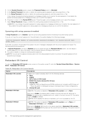
... set to confirm the deletion. NOTE: BIOS disables the device in three attempts, the system displays the following devices: ● None ● IDSDM ● SATA Ports in AHCI mode ● BOSS PCIe Cards (Internal M.2 Drives) ● Internal USB NOTE: RAID configurations and NVMe cards are not included, as BIOS does not have the ability to the boot list and OS. This option is not accessed by default. 22 Pre-operating system management applications In the Setup Password...
... set to confirm the deletion. NOTE: BIOS disables the device in three attempts, the system displays the following devices: ● None ● IDSDM ● SATA Ports in AHCI mode ● BOSS PCIe Cards (Internal M.2 Drives) ● Internal USB NOTE: RAID configurations and NVMe cards are not included, as BIOS does not have the ability to the boot list and OS. This option is not accessed by default. 22 Pre-operating system management applications In the Setup Password...
EMC BIOS and UEFI Reference Guide
Page 23
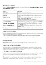
... set to set the time on the iDRAC settings utility needs the iDRAC Enterprise License upgrade. You can enable or disable various iDRAC parameters by default. LC is an interface to set to modify it for security and tracking purposes. iDRAC Settings utility The iDRAC settings utility is delivered as storage controllers or network cards. The Dell Lifecycle Controller is set up the Dell Lifecycle Controller, configuring hardware and firmware, and deploying the operating system, see Dell Integrated Dell Remote Access Controller User's Guide...
... set to set the time on the iDRAC settings utility needs the iDRAC Enterprise License upgrade. You can enable or disable various iDRAC parameters by default. LC is an interface to set to modify it for security and tracking purposes. iDRAC Settings utility The iDRAC settings utility is delivered as storage controllers or network cards. The Dell Lifecycle Controller is set up the Dell Lifecycle Controller, configuring hardware and firmware, and deploying the operating system, see Dell Integrated Dell Remote Access Controller User's Guide...


