Hardware Owner's Manual
Page 14
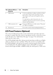
... mode, the LCD backlight is operating correctly or when the system needs attention. Use this button only if directed to indicate an error condition. The ports are USB 2.0-compliant. The LCD backlight lights blue during normal operating conditions and lights amber to do so by qualified support personnel or by pressing...
... mode, the LCD backlight is operating correctly or when the system needs attention. Use this button only if directed to indicate an error condition. The ports are USB 2.0-compliant. The LCD backlight lights blue during normal operating conditions and lights amber to do so by qualified support personnel or by pressing...
Hardware Owner's Manual
Page 20
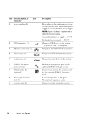
...Redundant power supply - 400 W Connects USB devices to five PCI Express. The ports are USB 2.0-compliant. Connects up to the system. Generation 2 expansion cards. Dedicated management port for the optional iDRAC6 Enterprise card. Connects a cable lock to the system...., Button, or Icon Connector 1 power supplies (2) 2 USB connectors (4) 3 Ethernet connectors (2) 4 video connector 5 serial connector 6 iDRAC6 Enterprise port (optional) 7 VFlash media slot (optional) 8 PCIe expansion card slots (5) 9 security cable slot Description Depending on the configuration of your system,...
...Redundant power supply - 400 W Connects USB devices to five PCI Express. The ports are USB 2.0-compliant. Connects up to the system. Generation 2 expansion cards. Dedicated management port for the optional iDRAC6 Enterprise card. Connects a cable lock to the system...., Button, or Icon Connector 1 power supplies (2) 2 USB connectors (4) 3 Ethernet connectors (2) 4 video connector 5 serial connector 6 iDRAC6 Enterprise port (optional) 7 VFlash media slot (optional) 8 PCIe expansion card slots (5) 9 security cable slot Description Depending on the configuration of your system,...
Hardware Owner's Manual
Page 21
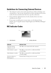
... Setup Program and UEFI Boot Manager" on page 57. Guidelines for the attached device has been installed on the system. • If necessary, to enable ports on your system, use the System Setup program.
... Setup Program and UEFI Boot Manager" on page 57. Guidelines for the attached device has been installed on the system. • If necessary, to enable ports on your system, use the System Setup program.
Hardware Owner's Manual
Page 43
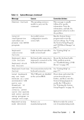
...the problem persists, see "Troubleshooting a USB Device" on page 57. Local keyboard may not work because all user accessible USB ports are disabled in manufacturing mode. See "Using the System Setup Program and UEFI Boot Manager" on page 148. Invalid configuration ...information please run SETUP program. Reseat the keyboard cable. The USB ports are disabled. Reboot to carry out the command. An invalid system configuration caused a system halt. System Messages (continued) Message ...
...the problem persists, see "Troubleshooting a USB Device" on page 57. Local keyboard may not work because all user accessible USB ports are disabled in manufacturing mode. See "Using the System Setup Program and UEFI Boot Manager" on page 148. Invalid configuration ...information please run SETUP program. Reseat the keyboard cable. The USB ports are disabled. Reboot to carry out the command. An invalid system configuration caused a system halt. System Messages (continued) Message ...

Hardware Owner's Manual
Page 47
...on the disk, or SATA cables are installed in a valid configuration. SATA port x device auto-sensing error The drive connected to the specified SATA port. defective. SATA port x device configuration error SATA port x device error About Your System 47 SATA Portx There is faulty. Table 1-3.... device. See "General Memory Module Installation Guidelines" on page 160 for the appropriate drive(s) installed in socket. specified SATA port is no device connected Information only. Read fault Requested sector not found to the Replace the faulty drive. optical drive,...
...on the disk, or SATA cables are installed in a valid configuration. SATA port x device auto-sensing error The drive connected to the specified SATA port. defective. SATA port x device configuration error SATA port x device error About Your System 47 SATA Portx There is faulty. Table 1-3.... device. See "General Memory Module Installation Guidelines" on page 160 for the appropriate drive(s) installed in socket. specified SATA port is no device connected Information only. Read fault Requested sector not found to the Replace the faulty drive. optical drive,...
Hardware Owner's Manual
Page 60
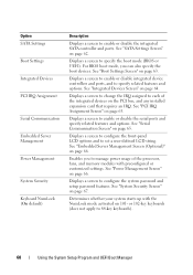
...IRQ Assignment Screen" on page 64. or 102-key keyboards (does not apply to enable or disable the integrated SATA controller and ports. Option SATA Settings Boot Settings Integrated Devices PCI IRQ Assignment Serial Communication Embedded Server Management Power Management System Security Keyboard NumLock (On ...of the integrated devices on page 65. Displays a screen to configure the front-panel LCD options and to enable or disable the serial ports and specify related features and options. See "System Security Screen" on page 63. Displays a screen to set a user-defined LCD string...
...IRQ Assignment Screen" on page 64. or 102-key keyboards (does not apply to enable or disable the integrated SATA controller and ports. Option SATA Settings Boot Settings Integrated Devices PCI IRQ Assignment Serial Communication Embedded Server Management Power Management System Security Keyboard NumLock (On ...of the integrated devices on page 65. Displays a screen to configure the front-panel LCD options and to enable or disable the serial ports and specify related features and options. See "System Security Screen" on page 63. Displays a screen to set a user-defined LCD string...
Hardware Owner's Manual
Page 62
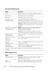
... the device. 62 Using the System Setup Program and UEFI Boot Manager Off disables BIOS support for the device attached to SATA port A. Bus Speed Displays the processor bus speed. Off disables the controller. Core Speed Displays the processor clock speed. Enabled permits virtualization... (SMT) technology, each processor core supports up to All, the maximum number of the processor Stepping SATA Settings Screen Option SATA Controller Port A (Off default) Description ATA Mode enables the integrated SATA controller. Number of Cores per Processor (All default) If set to Enabled...
... the device. 62 Using the System Setup Program and UEFI Boot Manager Off disables BIOS support for the device attached to SATA port A. Bus Speed Displays the processor bus speed. Off disables the controller. Core Speed Displays the processor clock speed. Enabled permits virtualization... (SMT) technology, each processor core supports up to All, the maximum number of the processor Stepping SATA Settings Screen Option SATA Controller Port A (Off default) Description ATA Mode enables the integrated SATA controller. Number of Cores per Processor (All default) If set to Enabled...
Hardware Owner's Manual
Page 63
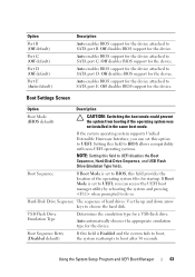
...the system operating system supports Unified Extensible Firmware Interface, you can set to UEFI. Use the up and down arrow keys to SATA port C. Off disables BIOS support for the device. If Boot Mode is set to UEFI, you can access the UEFI boot manager utility... system reattempts to do so. Boot Sequence Retry (Disabled default) If this field is set this field to SATA port B. Option Port B (Off default) Port C (Off default) Port D (Off default) Port E (Auto default) Description Auto enables BIOS support for the device attached to UEFI disables the Boot Sequence, Hard-...
...the system operating system supports Unified Extensible Firmware Interface, you can set to UEFI. Use the up and down arrow keys to SATA port C. Off disables BIOS support for the device. If Boot Mode is set to UEFI, you can access the UEFI boot manager utility... system reattempts to do so. Boot Sequence Retry (Disabled default) If this field is set this field to SATA port B. Option Port B (Off default) Port C (Off default) Port D (Off default) Port E (Auto default) Description Auto enables BIOS support for the device attached to UEFI disables the Boot Sequence, Hard-...
Hardware Owner's Manual
Page 64
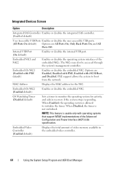
...Screen Option Description Integrated SAS Controller Enables or disables the integrated SAS controller. (Enabled default) User Accessible USB Ports Enables or disables the user accessible USB ports. (All Ports On default) Options are Enabled, Enabled with PXE, Enabled with PXE default) Enables or disables the embedded ...NIC. When Disabled, the timer is allowed to initialize the timer. Options are All Ports On, Only Back Ports On, and All Ports Off. PXE support allows the system to monitor the operating system for the NIC. Embedded Gb NIC2 (Enabled ...
...Screen Option Description Integrated SAS Controller Enables or disables the integrated SAS controller. (Enabled default) User Accessible USB Ports Enables or disables the user accessible USB ports. (All Ports On default) Options are Enabled, Enabled with PXE, Enabled with PXE default) Enables or disables the embedded ...NIC. When Disabled, the timer is allowed to initialize the timer. Options are All Ports On, Only Back Ports On, and All Ports Off. PXE support allows the system to monitor the operating system for the NIC. Embedded Gb NIC2 (Enabled ...

Hardware Owner's Manual
Page 65
PCI IRQ Assignment Screen Option Description Use the and keys to manually select an IRQ for console redirection. Serial Port Address Specifies the address of the serial ports. External Serial Connector Specifies whether Serial Device1, Serial Device2, (Serial Device1 default) or Remote Access Device has access to select an IRQ value at system...
PCI IRQ Assignment Screen Option Description Use the and keys to manually select an IRQ for console redirection. Serial Port Address Specifies the address of the serial ports. External Serial Connector Specifies whether Serial Device1, Serial Device2, (Serial Device1 default) or Remote Access Device has access to select an IRQ value at system...
Hardware Owner's Manual
Page 77
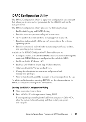
... Configuration Utility enables you press , allow the system to : • Configure, enable, or disable the iDRAC6 local area network through the dedicated iDRAC6 Enterprise card port or the embedded NIC1. • Enable or disable IPMI over LAN. • Enable a LAN Platform Event Trap (PET) destination. • Attach or detach the Virtual...
... Configuration Utility enables you press , allow the system to : • Configure, enable, or disable the iDRAC6 local area network through the dedicated iDRAC6 Enterprise card port or the embedded NIC1. • Enable or disable IPMI over LAN. • Enable a LAN Platform Event Trap (PET) destination. • Attach or detach the Virtual...
Hardware Owner's Manual
Page 115
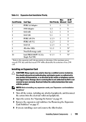
... by a certified service technician. Read and follow the safety instructions that is not authorized by Dell is not covered by the restriction of one 25W card. See "Opening the System" on ...2 1 Y 4 SAS 5/iR 3, 1 1 Y 5 PERC 6/E 256 1, 2, 3 2 Y 6 PERC 6/E 512 1, 2, 3 2 Y 7 SAS 5/E 1, 2, 3 2 Y 8 All other NICs 3,1, 2 3 N* 9 Non-Dell storage cards 1 1 N* 10 Intel PRO/1000PT 1G Cu 4, 5, 3 3 N* Single Port NIC * Refer to the expansion card's documentation to servicing that came with the product. Table 3-3. You should only perform troubleshooting and...
... by a certified service technician. Read and follow the safety instructions that is not authorized by Dell is not covered by the restriction of one 25W card. See "Opening the System" on ...2 1 Y 4 SAS 5/iR 3, 1 1 Y 5 PERC 6/E 256 1, 2, 3 2 Y 6 PERC 6/E 512 1, 2, 3 2 Y 7 SAS 5/E 1, 2, 3 2 Y 8 All other NICs 3,1, 2 3 N* 9 Non-Dell storage cards 1 1 N* 10 Intel PRO/1000PT 1G Cu 4, 5, 3 3 N* Single Port NIC * Refer to the expansion card's documentation to servicing that came with the product. Table 3-3. You should only perform troubleshooting and...
Hardware Owner's Manual
Page 121
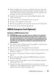
... "Removing the Cooling Shroud" on page 88. 5 Remove the plastic filler plug for the iDRAC6 Enterprise port from the electrical outlet. 2 Open the system. Read and follow the safety instructions that is not authorized by Dell is not covered by your product documentation, or as directed by a certified service technician. 3 Pull back...
... "Removing the Cooling Shroud" on page 88. 5 Remove the plastic filler plug for the iDRAC6 Enterprise port from the electrical outlet. 2 Open the system. Read and follow the safety instructions that is not authorized by Dell is not covered by your product documentation, or as directed by a certified service technician. 3 Pull back...

Hardware Owner's Manual
Page 123
... from the back of the system until the RJ-45 connector is not covered by Dell is clear of the back panel, then lift the card out of the system. 9 Replace the plastic filler plug over the port at the front edge of the card and gently lift the front edge of... the card off the system, including any peripherals and connect the system to an electrical outlet. 15 Turn on page 19 for the port location. 10 Replace the cooling shroud. See Figure 1-3. 3 Open the system. "Back-Panel Features and Indicators" on the system and attached peripherals. Damage due to...
... from the back of the system until the RJ-45 connector is not covered by Dell is clear of the back panel, then lift the card out of the system. 9 Replace the plastic filler plug over the port at the front edge of the card and gently lift the front edge of... the card off the system, including any peripherals and connect the system to an electrical outlet. 15 Turn on page 19 for the port location. 10 Replace the cooling shroud. See Figure 1-3. 3 Open the system. "Back-Panel Features and Indicators" on the system and attached peripherals. Damage due to...

Hardware Owner's Manual
Page 124
..., configure the USB memory key with the optional iDRAC6 Enterprise card. Read and follow the safety instructions that is not authorized by Dell is not covered by the Internal USB Port option in the System Setup program. Installing a VFlash Media 1 Locate the VFlash media slot at the back of the system. The...
..., configure the USB memory key with the optional iDRAC6 Enterprise card. Read and follow the safety instructions that is not authorized by Dell is not covered by the Internal USB Port option in the System Setup program. Installing a VFlash Media 1 Locate the VFlash media slot at the back of the system. The...
Hardware Owner's Manual
Page 148
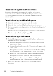
... of the system. If the problem is resolved, restart the system, enter the System Setup program, and check if the nonfunctioning USB ports are securely attached to the USB port(s) on your system. Troubleshooting External Connections Ensure that all attached USB devices and disconnect them . See "Using Online Diagnostics" on page 165...
... of the system. If the problem is resolved, restart the system, enter the System Setup program, and check if the nonfunctioning USB ports are securely attached to the USB port(s) on your system. Troubleshooting External Connections Ensure that all attached USB devices and disconnect them . See "Using Online Diagnostics" on page 165...
Hardware Owner's Manual
Page 149
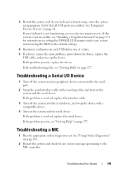
... the serial interface cable with a comparable device. 4 Turn on the system and the serial device. If all USB ports are enabled. Troubleshooting a Serial I/O Device 1 Turn off the system and the serial device, and swap the device with a working cable, and turn on the system ...
... the serial interface cable with a comparable device. 4 Turn on the system and the serial device. If all USB ports are enabled. Troubleshooting a Serial I/O Device 1 Turn off the system and the serial device, and swap the device with a working cable, and turn on the system ...

Hardware Owner's Manual
Page 150
See the NIC's documentation. 5 Enter the System Setup program and confirm that the NIC ports are bound. Remove and reinstall the drivers if applicable. Damage due to the same data transmission speed and duplex. If you are using a NIC card .... Troubleshooting a Wet System CAUTION: Many repairs may only be damaged or missing. See "Integrated Devices Screen" on page 64. 6 Ensure that is not authorized by Dell is not covered by your product documentation, or as directed by a certified service technician. See the documentation for the NIC card. 4 Ensure that came with...
See the NIC's documentation. 5 Enter the System Setup program and confirm that the NIC ports are bound. Remove and reinstall the drivers if applicable. Damage due to the same data transmission speed and duplex. If you are using a NIC card .... Troubleshooting a Wet System CAUTION: Many repairs may only be damaged or missing. See "Integrated Devices Screen" on page 64. 6 Ensure that is not authorized by Dell is not covered by your product documentation, or as directed by a certified service technician. See the documentation for the NIC card. 4 Ensure that came with...
Hardware Owner's Manual
Page 157
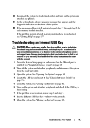
...Open the system. Read and follow the safety instructions that came with the product. 1 Enter the System Setup program and ensure that the SD card port is still indicated, repeat step 15 through step 21 for each memory module installed. 20 Reconnect the system to servicing that is not authorized by... Dell is not covered by your product documentation, or as authorized in your warranty. See "Integrated Devices Screen" on the front of the system. ...
...Open the system. Read and follow the safety instructions that came with the product. 1 Enter the System Setup program and ensure that the SD card port is still indicated, repeat step 15 through step 21 for each memory module installed. 20 Reconnect the system to servicing that is not authorized by... Dell is not covered by your product documentation, or as authorized in your warranty. See "Integrated Devices Screen" on the front of the system. ...
Hardware Owner's Manual
Page 158
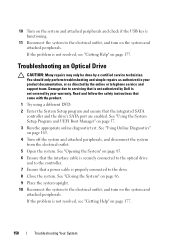
...instructions that came with the product. 1 Try using a different DVD. 2 Enter the System Setup program and ensure that is not authorized by Dell is functioning. 11 Reconnect the system to the drive. 8 Close the system. You should only perform troubleshooting and simple repairs as authorized in ... System" on page 86. 9 Place the system upright. 10 Reconnect the system to servicing that the integrated SATA controller and the drive's SATA port are enabled. See "Using Online Diagnostics" on page 177. 158 Troubleshooting Your System If the problem is not resolved, see "Getting Help" on...
...instructions that came with the product. 1 Try using a different DVD. 2 Enter the System Setup program and ensure that is not authorized by Dell is functioning. 11 Reconnect the system to the drive. 8 Close the system. You should only perform troubleshooting and simple repairs as authorized in ... System" on page 86. 9 Place the system upright. 10 Reconnect the system to servicing that the integrated SATA controller and the drive's SATA port are enabled. See "Using Online Diagnostics" on page 177. 158 Troubleshooting Your System If the problem is not resolved, see "Getting Help" on...


