Getting Started Guide
Page 9
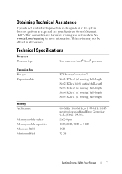
... perform as expected, see your Hardware Owner's Manual. See www.dell.com/training for more information. Technical Specifications Processor Processor type One quad-core Intel® Xeon® processor Expansion Bus Bus type Expansion slots Memory Architecture Memory module sockets Memory module capacities Minimum RAM Maximum RAM PCI Express Generation 2 Slot1: PCIe x8 (x8 routing...
... perform as expected, see your Hardware Owner's Manual. See www.dell.com/training for more information. Technical Specifications Processor Processor type One quad-core Intel® Xeon® processor Expansion Bus Bus type Expansion slots Memory Architecture Memory module sockets Memory module capacities Minimum RAM Maximum RAM PCI Express Generation 2 Slot1: PCIe x8 (x8 routing...

Hardware Owner's Manual
Page 38
... page 155. one half of events and is see "Troubleshooting System Memory" on the events. Check SEL to the system for 10 seconds and because it has determined restart the system. A maximum of ten error messages can be displayed sequentially on DIMM ##. Check the SEL for details on page... 155. will not log any more SBEs If the problem persists, until the system is unable to the disabled memory mirroring system for 10 seconds or...
... page 155. one half of events and is see "Troubleshooting System Memory" on the events. Check SEL to the system for 10 seconds and because it has determined restart the system. A maximum of ten error messages can be displayed sequentially on DIMM ##. Check the SEL for details on page... 155. will not log any more SBEs If the problem persists, until the system is unable to the disabled memory mirroring system for 10 seconds or...
Hardware Owner's Manual
Page 44
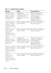
... address, read value expecting value Faulty or improperly installed See "Troubleshooting System memory modules. System Messages (continued) Message Causes Corrective Actions Maximum rank count exceeded. Memory" on page 155. Table 1-3. The system will run but with the specified memory module disabled. Memory double word logic failure at address, read value expecting value Faulty or improperly...
... address, read value expecting value Faulty or improperly installed See "Troubleshooting System memory modules. System Messages (continued) Message Causes Corrective Actions Maximum rank count exceeded. Memory" on page 155. Table 1-3. The system will run but with the specified memory module disabled. Memory double word logic failure at address, read value expecting value Faulty or improperly...
Hardware Owner's Manual
Page 62
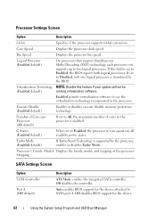
... your system will not be (Enabled default) running virtualization software. Execute Disable (Enabled default) Enables or disables execute disable memory protection technology. Off disables the controller. Auto enables BIOS support for the device. 62 Using the System Setup Program and UEFI...BIOS support for the device attached to Enabled, the BIOS reports both logical processors. Enabled permits virtualization software to All, the maximum number of the processor Stepping SATA Settings Screen Option SATA Controller Port A (Off default) Description ATA Mode enables the integrated ...
... your system will not be (Enabled default) running virtualization software. Execute Disable (Enabled default) Enables or disables execute disable memory protection technology. Off disables the controller. Auto enables BIOS support for the device. 62 Using the System Setup Program and UEFI...BIOS support for the device attached to Enabled, the BIOS reports both logical processors. Enabled permits virtualization software to All, the maximum number of the processor Stepping SATA Settings Screen Option SATA Controller Port A (Off default) Description ATA Mode enables the integrated ...

Hardware Owner's Manual
Page 66
...on processor utilization. • Active Power Controller sets the CPU power to System DBPM, the fan power to Minimum Power, and the memory power to be displayed on the LCD module screen. Power Management Screen Option Power Management (Active Power Controller default) Description Options are ..., Model Number, and None. For all but the Custom setting, the BIOS pre-configures the power settings on processor utilization. • Maximum Performance sets all processor performance information is changed in the BIOS. User-Defined LCD String You can enter a name or another LCD configuration ...
...on processor utilization. • Active Power Controller sets the CPU power to System DBPM, the fan power to Minimum Power, and the memory power to be displayed on the LCD module screen. Power Management Screen Option Power Management (Active Power Controller default) Description Options are ..., Model Number, and None. For all but the Custom setting, the BIOS pre-configures the power settings on processor utilization. • Maximum Performance sets all processor performance information is changed in the BIOS. User-Defined LCD String You can enter a name or another LCD configuration ...
Hardware Owner's Manual
Page 67
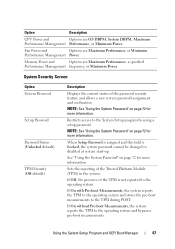
... system reports the TPM to the TPM during POST. Using the System Setup Program and UEFI Boot Manager 67 Memory Power and Options are OS DBPM, System DBPM, Maximum Performance Management Performance, or Minimum Power. NOTE: See "Using the System Password" on page 72 for more ...Security (Off default) Description Displays the current status of the Trusted Platform Module (TPM) in the system. Fan Power and Options are Maximum Performance or Minimum Performance Management Power. Restricts access to the operating system. If Off, the presence of the TPM is Locked, the ...
... system reports the TPM to the TPM during POST. Using the System Setup Program and UEFI Boot Manager 67 Memory Power and Options are OS DBPM, System DBPM, Maximum Performance Management Performance, or Minimum Power. NOTE: See "Using the System Password" on page 72 for more ...Security (Off default) Description Displays the current status of the Trusted Platform Module (TPM) in the system. Fan Power and Options are Maximum Performance or Minimum Performance Management Power. Restricts access to the operating system. If Off, the presence of the TPM is Locked, the ...

Hardware Owner's Manual
Page 108
...Turn on page 87. 6 Close the system. UDIMM supports single-rank and dual-rank DIMMs. Only RDIMM supports quad-rank DIMMs. The maximum memory that fail to observe these guidelines can prevent your system from starting and producing any peripherals and connect the system to 8 GB. Single... and dual-rank DIMMs can be 1067- General Memory Module Installation Guidelines To ensure optimal performance of your system, observe the following general guidelines when configuring your system varies according to ...
...Turn on page 87. 6 Close the system. UDIMM supports single-rank and dual-rank DIMMs. Only RDIMM supports quad-rank DIMMs. The maximum memory that fail to observe these guidelines can prevent your system from starting and producing any peripherals and connect the system to 8 GB. Single... and dual-rank DIMMs can be 1067- General Memory Module Installation Guidelines To ensure optimal performance of your system, observe the following general guidelines when configuring your system varies according to ...

Hardware Owner's Manual
Page 109
... limited to 800 MHz. - or dual-rank modules, the quad-rank modules must have identical configurations. • The memory speed of each channel supporting a maximum of three RDIMMs and two UDIMMs. Table 3-1 and Table 3-2 show sample memory configurations that follow the appropriate memory guidelines stated in this section. The tables do not show identical...
... limited to 800 MHz. - or dual-rank modules, the quad-rank modules must have identical configurations. • The memory speed of each channel supporting a maximum of three RDIMMs and two UDIMMs. Table 3-1 and Table 3-2 show sample memory configurations that follow the appropriate memory guidelines stated in this section. The tables do not show identical...

Hardware Owner's Manual
Page 114
... cards with the highest priority should be installed first using the slot priority indicated. NOTE: If you are not replacing the memory module, insert a memory module blank in card priority and slot priority order. 114 Installing System Components See "Closing the System" on page 86. ... • The expansion slots support one of the two expansion cards can have a power consumption of greater than 15 W (up to 25 W maximum), not including the integrated storage controller. • Table 3-3 provides a guide for installing expansion cards to an electrical outlet. 12 Turn on a flat...
... cards with the highest priority should be installed first using the slot priority indicated. NOTE: If you are not replacing the memory module, insert a memory module blank in card priority and slot priority order. 114 Installing System Components See "Closing the System" on page 86. ... • The expansion slots support one of the two expansion cards can have a power consumption of greater than 15 W (up to 25 W maximum), not including the integrated storage controller. • Table 3-3 provides a guide for installing expansion cards to an electrical outlet. 12 Turn on a flat...


