Getting Started Guide
Page 11
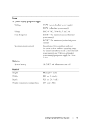
... operating range, the inrush current may reach 25A (redundant power supply) and 35A (non-redundant power supply) per power supply for 10 ms or less. Batteries System battery CR 2032 3.0-V lithium ion coin cell Physical Height Width Depth Weight (maximum configuration) 44 cm (17.3 inch) 21.8 cm (8.6 inch) 52.1 cm (20.5 inch...
... operating range, the inrush current may reach 25A (redundant power supply) and 35A (non-redundant power supply) per power supply for 10 ms or less. Batteries System battery CR 2032 3.0-V lithium ion coin cell Physical Height Width Depth Weight (maximum configuration) 44 cm (17.3 inch) 21.8 cm (8.6 inch) 52.1 cm (20.5 inch...
Hardware Owner's Manual
Page 9
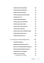
Troubleshooting a Damaged System 152 Troubleshooting the System Battery 152 Troubleshooting Power Supplies 153 Troubleshooting System Cooling Problems 154 Troubleshooting a Fan 154 Troubleshooting System Memory 155 Troubleshooting an Internal USB Key 157 Troubleshooting an ...
Troubleshooting a Damaged System 152 Troubleshooting the System Battery 152 Troubleshooting Power Supplies 153 Troubleshooting System Cooling Problems 154 Troubleshooting a Fan 154 Troubleshooting System Memory 155 Troubleshooting an Internal USB Key 157 Troubleshooting an ...
Hardware Owner's Manual
Page 27
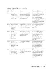
... E1116 Memory disabled, temp above range. See "Troubleshooting System Cooling Problems" on page 163. E1210 Motherboard battery failure. E1216 3.3V Regulator failure. Power cycle AC. E1211 RAID Controller battery failure. Reseat PCIe cards. 3.3V voltage regulator has failed. Remove and reseat the PCIe expansion cards. ...See "Troubleshooting the or the voltage is either missing, bad, or unable to recharge due to the components. Check battery. Memory has exceeded allowable temperature and has been disabled to prevent damage to thermal issues. Remove AC power to the...
... E1116 Memory disabled, temp above range. See "Troubleshooting System Cooling Problems" on page 163. E1210 Motherboard battery failure. E1216 3.3V Regulator failure. Power cycle AC. E1211 RAID Controller battery failure. Reseat PCIe cards. 3.3V voltage regulator has failed. Remove and reseat the PCIe expansion cards. ...See "Troubleshooting the or the voltage is either missing, bad, or unable to recharge due to the components. Check battery. Memory has exceeded allowable temperature and has been disabled to prevent damage to thermal issues. Remove AC power to the...
Hardware Owner's Manual
Page 39
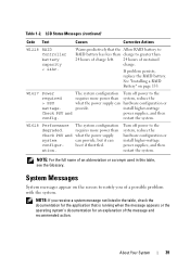
..., reduce the hardware configuration or install higher-wattage power supplies, and then restart the system. If problem persists, replace the RAID battery. The system configuration requires more power than what the power supply can provide, but it can provide. The system configuration requires more...for an explanation of an abbreviation or acronym used in the table, check the documentation for the application that the Allow RAID battery to RAID battery has less than charge to the system, reduce the hardware configuration or install higher-wattage power supplies, and then restart the...
..., reduce the hardware configuration or install higher-wattage power supplies, and then restart the system. If problem persists, replace the RAID battery. The system configuration requires more power than what the power supply can provide, but it can provide. The system configuration requires more...for an explanation of an abbreviation or acronym used in the table, check the documentation for the application that the Allow RAID battery to RAID battery has less than charge to the system, reduce the hardware configuration or install higher-wattage power supplies, and then restart the...

Hardware Owner's Manual
Page 49
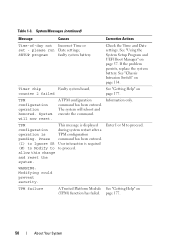
...and rank count: x,x,... The following DIMMs should match in size, number of ranks, or number of -day clock stopped Faulty battery or faulty chip. About Your System 49 See "General Memory Module Installation Guidelines" on page 152. Thermal sensor A memory ...module without a Replace the memory module. See "Troubleshooting the System Battery" on page 108. Causes Corrective Actions Invalid memory configuration. Time-of data lanes. The following DIMMs should match in geometry: x,x,... ...
...and rank count: x,x,... The following DIMMs should match in size, number of ranks, or number of -day clock stopped Faulty battery or faulty chip. About Your System 49 See "General Memory Module Installation Guidelines" on page 152. Thermal sensor A memory ...module without a Replace the memory module. See "Troubleshooting the System Battery" on page 108. Causes Corrective Actions Invalid memory configuration. Time-of data lanes. The following DIMMs should match in geometry: x,x,... ...
Hardware Owner's Manual
Page 50
...during system restart after a TPM configuration command has been entered. TPM failure A Trusted Platform Module See "Getting Help" on page 177. SETUP program faulty system battery. counter 2 failed See "Getting Help" on (TPM) function has failed. page 177. 50 About Your System The system will now reset. WARNING: Modifying could... the system. Table 1-3. See "Using the System Setup Program and UEFI Boot Manager" on page 134. If the problem persists, replace the system battery. System will reboot and execute the command. TPM configuration operation is pending.
...during system restart after a TPM configuration command has been entered. TPM failure A Trusted Platform Module See "Getting Help" on page 177. SETUP program faulty system battery. counter 2 failed See "Getting Help" on (TPM) function has failed. page 177. 50 About Your System The system will now reset. WARNING: Modifying could... the system. Table 1-3. See "Using the System Setup Program and UEFI Boot Manager" on page 134. If the problem persists, replace the system battery. System will reboot and execute the command. TPM configuration operation is pending.
Hardware Owner's Manual
Page 130
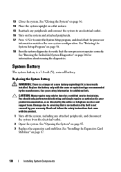
... page 85. 3 Replace the expansion card stabilizer. 13 Close the system. See "Entering the System Setup Program" on page 166 for additional info. System Battery The system battery is incorrectly installed. You should only perform troubleshooting and simple repairs as directed by the manufacturer. See "Opening the System" on page 87. 130... may only be done by your product documentation, or as authorized in your warranty. Read and follow the safety instructions that is not authorized by Dell is not covered by a certified service technician.
... page 85. 3 Replace the expansion card stabilizer. 13 Close the system. See "Entering the System Setup Program" on page 166 for additional info. System Battery The system battery is incorrectly installed. You should only perform troubleshooting and simple repairs as directed by the manufacturer. See "Opening the System" on page 87. 130... may only be done by your product documentation, or as authorized in your warranty. Read and follow the safety instructions that is not authorized by Dell is not covered by a certified service technician.

Hardware Owner's Manual
Page 131
...Installing System Components 131 See "Removing an Expansion Card" on page 170. Replacing the System Battery 1 2 3 1 positive side of battery connector 3 negative side of the connector. 8 Install the new battery by pressing down firmly on page 115. 12 Install the expansion card stabilizer. See "...24. CAUTION: To avoid damage to the battery connector, you must firmly support the connector while installing or removing a battery. 6 Support the battery connector by pressing down firmly on the positive side of the connector. 7 Press the battery toward the positive side of the connector ...
...Installing System Components 131 See "Removing an Expansion Card" on page 170. Replacing the System Battery 1 2 3 1 positive side of battery connector 3 negative side of the connector. 8 Install the new battery by pressing down firmly on page 115. 12 Install the expansion card stabilizer. See "...24. CAUTION: To avoid damage to the battery connector, you must firmly support the connector while installing or removing a battery. 6 Support the battery connector by pressing down firmly on the positive side of the connector. 7 Press the battery toward the positive side of the connector ...
Hardware Owner's Manual
Page 132
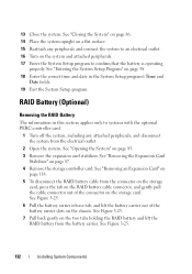
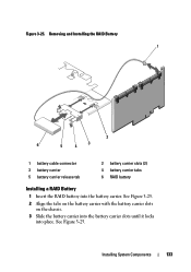
...25. 7 Pull back gently on the two tabs holding the RAID battery and lift the RAID battery from the electrical outlet. 2 Open the system. See Figure 3-25. 132 Installing System Components RAID Battery (Optional) Removing the RAID Battery The information in the System Setup program's Time and Date fields....program to systems with the optional PERC controller card. 1 Turn off the system, including any attached peripherals, and disconnect the system from the battery carrier. See "Closing the System" on page 86. 14 Place the system upright on a flat surface. 15 Reattach any peripherals and ...
...25. 7 Pull back gently on the two tabs holding the RAID battery and lift the RAID battery from the electrical outlet. 2 Open the system. See Figure 3-25. 132 Installing System Components RAID Battery (Optional) Removing the RAID Battery The information in the System Setup program's Time and Date fields....program to systems with the optional PERC controller card. 1 Turn off the system, including any attached peripherals, and disconnect the system from the battery carrier. See "Closing the System" on page 86. 14 Place the system upright on a flat surface. 15 Reattach any peripherals and ...
Hardware Owner's Manual
Page 133
Installing System Components 133 Figure 3-25. See Figure 3-25. See Figure 3-25. 2 Align the tabs on the battery carrier with the battery carrier slots on the chassis. 3 Slide the battery carrier into the battery carrier slots until it locks into the battery carrier. Removing and Installing the RAID Battery 1 2 6 3 5 4 1 battery cable connector 3 battery carrier 5 battery carrier release tab 2 battery carrier slots (2) 4 battery carrier tabs 6 RAID battery Installing a RAID Battery 1 Insert the RAID battery into place.
Installing System Components 133 Figure 3-25. See Figure 3-25. See Figure 3-25. 2 Align the tabs on the battery carrier with the battery carrier slots on the chassis. 3 Slide the battery carrier into the battery carrier slots until it locks into the battery carrier. Removing and Installing the RAID Battery 1 2 6 3 5 4 1 battery cable connector 3 battery carrier 5 battery carrier release tab 2 battery carrier slots (2) 4 battery carrier tabs 6 RAID battery Installing a RAID Battery 1 Insert the RAID battery into place.

Hardware Owner's Manual
Page 134
Read and follow the safety instructions that is not authorized by Dell is not covered by a certified service technician. See "Installing an Expansion Card" on page 87. 6 Close the system. See "Installing the Expansion Card Stabilizer" on ... on the storage card and replace the storage controller card. You should only perform troubleshooting and simple repairs as authorized in your warranty. 4 Connect the battery cable to the connector on the system and attached peripherals.
Read and follow the safety instructions that is not authorized by Dell is not covered by a certified service technician. See "Installing an Expansion Card" on page 87. 6 Close the system. See "Installing the Expansion Card Stabilizer" on ... on the storage card and replace the storage controller card. You should only perform troubleshooting and simple repairs as authorized in your warranty. 4 Connect the battery cable to the connector on the system and attached peripherals.

Hardware Owner's Manual
Page 152
...your product documentation, or as directed by a certified service technician. Read and follow the safety instructions that is not authorized by Dell is not covered by the online or telephone service and support team. See "Using Online Diagnostics" on page 85. 3 Ensure...8226; Processor and heat sink • Memory modules • Hard-drive carriers 4 Ensure that came with the product. Troubleshooting the System Battery CAUTION: Many repairs may lose its system configuration information. Read and follow the safety instructions that all cables are properly connected. 5 Close the...
...your product documentation, or as directed by a certified service technician. Read and follow the safety instructions that is not authorized by Dell is not covered by the online or telephone service and support team. See "Using Online Diagnostics" on page 85. 3 Ensure...8226; Processor and heat sink • Memory modules • Hard-drive carriers 4 Ensure that came with the product. Troubleshooting the System Battery CAUTION: Many repairs may lose its system configuration information. Read and follow the safety instructions that all cables are properly connected. 5 Close the...
Hardware Owner's Manual
Page 153
... "Chassis Intrusion Switch" on page 177. Operating the system with only one power supply must be caused by software rather than by replacing the battery, see "Getting Help" on page 130. 1 Re-enter the time and date through the System Setup program. If the system seems to operate normally ... 153 If the problem persists, replace the faulty power supply. 3 If the problem persists, see "Getting Help" on page 134. See "Replacing the System Battery" on page 177. If the date and time are not correct in the System Setup program, the problem may cause the system time to signify...
... "Chassis Intrusion Switch" on page 177. Operating the system with only one power supply must be caused by software rather than by replacing the battery, see "Getting Help" on page 130. 1 Re-enter the time and date through the System Setup program. If the system seems to operate normally ... 153 If the problem persists, replace the faulty power supply. 3 If the problem persists, see "Getting Help" on page 134. See "Replacing the System Battery" on page 177. If the date and time are not correct in the System Setup program, the problem may cause the system time to signify...
Hardware Owner's Manual
Page 161
.... See "Opening the System" on page 57. 3 Restart the system and press the applicable key sequence to servicing that is not authorized by Dell is enabled. See "Using Online Diagnostics" on page 165. 2 Enter the System Setup program and ensure that came with the product. 5 Turn...online diagnostic test. See "Removing the Cooling Shroud" on page 88. 8 Ensure that the RAID battery is properly connected and, if applicable, the memory module on page 115 9 If you have a battery-cached PERC controller, ensure that the controller card is properly seated. Troubleshooting a SAS or SAS ...
.... See "Opening the System" on page 57. 3 Restart the system and press the applicable key sequence to servicing that is not authorized by Dell is enabled. See "Using Online Diagnostics" on page 165. 2 Enter the System Setup program and ensure that came with the product. 5 Turn...online diagnostic test. See "Removing the Cooling Shroud" on page 88. 8 Ensure that the RAID battery is properly connected and, if applicable, the memory module on page 115 9 If you have a battery-cached PERC controller, ensure that the controller card is properly seated. Troubleshooting a SAS or SAS ...

Hardware Owner's Manual
Page 186
... manage system resources-memory, disk drives, or printers, for example. VAC - Video graphics array. When such devices are video standards for example) is running. U-DIMM - A battery-powered unit that provides (in a series, you must support the resolution. 186 Glossary USB devices can display (with the monitor) your monitor must install the...
... manage system resources-memory, disk drives, or printers, for example. VAC - Video graphics array. When such devices are video standards for example) is running. U-DIMM - A battery-powered unit that provides (in a series, you must support the resolution. 186 Glossary USB devices can display (with the monitor) your monitor must install the...
Hardware Owner's Manual
Page 189
... battery, 161 battery (system) replacing, 130 blank hard drive, 90 BMC configuring, 76 C CD drive troubleshooting, 158 connectors USB, 12, 19 video, 12, 19 contacting Dell, 177 control panel assembly features, 12 installing, 138 LCD panel features, 14 removing, 136 cooling fans troubleshooting, 154 cover closing, 86 D damaged systems troubleshooting, 152 Dell contacting, 177 Dell PowerEdge...
... battery, 161 battery (system) replacing, 130 blank hard drive, 90 BMC configuring, 76 C CD drive troubleshooting, 158 connectors USB, 12, 19 video, 12, 19 contacting Dell, 177 control panel assembly features, 12 installing, 138 LCD panel features, 14 removing, 136 cooling fans troubleshooting, 154 cover closing, 86 D damaged systems troubleshooting, 152 Dell contacting, 177 Dell PowerEdge...

Hardware Owner's Manual
Page 191
... a drive carrier, 94 hard drives, 91 memory modules, 113 power supply, 103, 105 processor, 126 SAS backplane board, 138 replacing power supply, 104, 106 system battery, 130 Index 191 troubleshooting, 155 memory key connector (USB), 124 memory modules (DIMMs) configuring, 108 installing, 111 removing, 113 messages error messages, 58 status LCD...
... a drive carrier, 94 hard drives, 91 memory modules, 113 power supply, 103, 105 processor, 126 SAS backplane board, 138 replacing power supply, 104, 106 system battery, 130 Index 191 troubleshooting, 155 memory key connector (USB), 124 memory modules (DIMMs) configuring, 108 installing, 111 removing, 113 messages error messages, 58 status LCD...
Hardware Owner's Manual
Page 192
startup accessing system features, 11 support contacting Dell, 177 system closing, 86 system cooling troubleshooting, 154 system features accessing, 11 system password, 72 system setup options, 59 system setup program CPU options, 62 ... serial communications options, 65-66 system security options, 67 system setup screens main, 59 system startup failure, 147 T telephone numbers, 177 TPM security, 67 troubleshooting battery, 152 CD drive, 158 cooling fans, 154 damaged system, 152 expansion card, 162 external connections, 148 hard drive, 160 internal USB key, 157 keyboard, 148...
startup accessing system features, 11 support contacting Dell, 177 system closing, 86 system cooling troubleshooting, 154 system features accessing, 11 system password, 72 system setup options, 59 system setup program CPU options, 62 ... serial communications options, 65-66 system security options, 67 system setup screens main, 59 system startup failure, 147 T telephone numbers, 177 TPM security, 67 troubleshooting battery, 152 CD drive, 158 cooling fans, 154 damaged system, 152 expansion card, 162 external connections, 148 hard drive, 160 internal USB key, 157 keyboard, 148...


