
Information Update - Power Infrastructure Sizing
Page 1
... guidance is specific to the system configuration and to the workload expected of the power supply power rating. On-line capacity planning tools available from Dell system management software provide additional predictability for a particular system configuration. If the power supply power rating for a system is rated at the 500W value also provides additional assurance that...
... guidance is specific to the system configuration and to the workload expected of the power supply power rating. On-line capacity planning tools available from Dell system management software provide additional predictability for a particular system configuration. If the power supply power rating for a system is rated at the 500W value also provides additional assurance that...

Getting Started Guide
Page 6
Plug the other end of the power cable(s) into a loop as an uninterrupted power supply (UPS) or a power distribution unit (PDU). 4 Getting Started With Your System Connecting the Power Cable(s) Connect the system's power cable(s) to the system and, if a monitor is used, connect the monitor's power cable to the monitor. Securing the Power Cable(s) Bend the system power cable(s) into a grounded electrical outlet or a separate power source such as shown in the illustration and secure the cable(s) with the provided strap.
Plug the other end of the power cable(s) into a loop as an uninterrupted power supply (UPS) or a power distribution unit (PDU). 4 Getting Started With Your System Connecting the Power Cable(s) Connect the system's power cable(s) to the system and, if a monitor is used, connect the monitor's power cable to the monitor. Securing the Power Cable(s) Bend the system power cable(s) into a grounded electrical outlet or a separate power source such as shown in the illustration and secure the cable(s) with the provided strap.
Getting Started Guide
Page 7
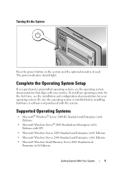
...; Microsoft Windows Server® 2008 Standard and Enterprise (x86) Editions with the system. Turning On the System Press the power button on the system and the optional monitor, if used. The power indicators should light. Complete the Operating System Setup If you purchased a preinstalled operating system, see the installation and configuration documentation...
...; Microsoft Windows Server® 2008 Standard and Enterprise (x86) Editions with the system. Turning On the System Press the power button on the system and the optional monitor, if used. The power indicators should light. Complete the Operating System Setup If you purchased a preinstalled operating system, see the installation and configuration documentation...
Getting Started Guide
Page 11
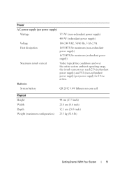
... configuration) 44 cm (17.3 inch) 21.8 cm (8.6 inch) 52.1 cm (20.5 inch) 23.5 kg (51.8 lb) Getting Started With Your System 9 Power AC power supply (per power supply) Wattage 375 W (non-redundant power supply) 400 W (redundant power supply) Voltage 100-240 VAC, 50/60 Hz, 5.8A-2.9A Heat dissipation 1683 BTU/hr maximum (non-redundant...
... configuration) 44 cm (17.3 inch) 21.8 cm (8.6 inch) 52.1 cm (20.5 inch) 23.5 kg (51.8 lb) Getting Started With Your System 9 Power AC power supply (per power supply) Wattage 375 W (non-redundant power supply) 400 W (redundant power supply) Voltage 100-240 VAC, 50/60 Hz, 5.8A-2.9A Heat dissipation 1683 BTU/hr maximum (non-redundant...
Hardware Owner's Manual
Page 3
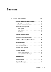
Contents 1 About Your System 11 Accessing System Features During Startup 11 Front-Panel Features and Indicators 12 LCD Panel Features (Optional 14 Home Screen 15 Setup Menu 16 View Menu 17 Hard-Drive Indicator Patterns 18 Back-Panel Features and Indicators 19 Guidelines for Connecting External Devices 21 NIC Indicator Codes 21 Power Indicator Codes 22 Diagnostic Lights (Optional 23 LCD Status Messages 25 Viewing Status Messages 26 Removing LCD Status Messages 26 System Messages 39 Warning Messages 54 Diagnostics Messages 54 Contents 3
Contents 1 About Your System 11 Accessing System Features During Startup 11 Front-Panel Features and Indicators 12 LCD Panel Features (Optional 14 Home Screen 15 Setup Menu 16 View Menu 17 Hard-Drive Indicator Patterns 18 Back-Panel Features and Indicators 19 Guidelines for Connecting External Devices 21 NIC Indicator Codes 21 Power Indicator Codes 22 Diagnostic Lights (Optional 23 LCD Status Messages 25 Viewing Status Messages 26 Removing LCD Status Messages 26 System Messages 39 Warning Messages 54 Diagnostics Messages 54 Contents 3
Hardware Owner's Manual
Page 4
... Screen 62 Boot Settings Screen 63 Integrated Devices Screen 64 PCI IRQ Assignment Screen 65 Serial Communication Screen 65 Embedded Server Management Screen (Optional 66 Power Management Screen 66 System Security Screen 67 Exit Screen 69 Entering the UEFI Boot Manager 69 Using the UEFI Boot Manager Navigation Keys 70 UEFI...
... Screen 62 Boot Settings Screen 63 Integrated Devices Screen 64 PCI IRQ Assignment Screen 65 Serial Communication Screen 65 Embedded Server Management Screen (Optional 66 Power Management Screen 66 System Security Screen 67 Exit Screen 69 Entering the UEFI Boot Manager 69 Using the UEFI Boot Manager Navigation Keys 70 UEFI...

Hardware Owner's Manual
Page 6
... Drives 99 Removing an Optical or a Tape Drive 99 Installing an Optical or Tape Drive 100 Power Supplies 103 Removing a Redundant Power Supply 103 Installing a Redundant Power Supply 104 Removing a Non-Redundant Power Supply . . . 105 Installing a Non-Redundant Power Supply . . . . 106 System Fan 106 Removing the System Fan 106 Installing the System Fan 107 System...
... Drives 99 Removing an Optical or a Tape Drive 99 Installing an Optical or Tape Drive 100 Power Supplies 103 Removing a Redundant Power Supply 103 Installing a Redundant Power Supply 104 Removing a Non-Redundant Power Supply . . . 105 Installing a Non-Redundant Power Supply . . . . 106 System Fan 106 Removing the System Fan 106 Installing the System Fan 107 System...
Hardware Owner's Manual
Page 8
... 136 Installing the Control Panel Assembly 138 SAS Backplane 138 Removing the SAS Backplane 138 Installing the SAS Backplane 140 Power Distribution Board 140 Removing the Power Distribution Board . . . . . 140 Replacing the Power Distribution Board . . . . . 142 System Board 142 Removing the System Board 142 Installing the System Board 144 4 Troubleshooting Your System 147...
... 136 Installing the Control Panel Assembly 138 SAS Backplane 138 Removing the SAS Backplane 138 Installing the SAS Backplane 140 Power Distribution Board 140 Removing the Power Distribution Board . . . . . 140 Replacing the Power Distribution Board . . . . . 142 System Board 142 Removing the System Board 142 Installing the System Board 144 4 Troubleshooting Your System 147...
Hardware Owner's Manual
Page 9
Troubleshooting a Damaged System 152 Troubleshooting the System Battery 152 Troubleshooting Power Supplies 153 Troubleshooting System Cooling Problems 154 Troubleshooting a Fan 154 Troubleshooting System Memory 155 Troubleshooting an Internal USB Key 157 Troubleshooting an Optical Drive 158 ...
Troubleshooting a Damaged System 152 Troubleshooting the System Battery 152 Troubleshooting Power Supplies 153 Troubleshooting System Cooling Problems 154 Troubleshooting a Fan 154 Troubleshooting System Memory 155 Troubleshooting an Internal USB Key 157 Troubleshooting an Optical Drive 158 ...
Hardware Owner's Manual
Page 10
Selecting Diagnostics Options 167 Viewing Information and Results 168 6 Jumpers and Connectors 169 System Board Jumpers 169 System Board Connectors 170 SAS Backplane Board Connectors 173 Power Distribution Board Connectors 174 Disabling a Forgotten Password 174 7 Getting Help 177 Contacting Dell 177 Glossary 179 Index 189 10 Contents
Selecting Diagnostics Options 167 Viewing Information and Results 168 6 Jumpers and Connectors 169 System Board Jumpers 169 System Board Connectors 170 SAS Backplane Board Connectors 173 Power Distribution Board Connectors 174 Disabling a Forgotten Password 174 7 Getting Help 177 Contacting Dell 177 Glossary 179 Index 189 10 Contents
Hardware Owner's Manual
Page 13
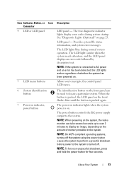
.... Allows you to navigate the control panel LCD menu. 6 System identification button 7 Power-on indicator, power button The identification button on indicator lights when the system power is connected to AC power and an error has been detected, the LCD lights amber regardless of memory installed in... the system. NOTE: On ACPI-compliant operating systems, turning off . The LCD lights blue during system startup. NOTE: When powering on . See "Diagnostic Lights (Optional)" on . NOTE: If the system is on the system, the video monitor can be used to the...
.... Allows you to navigate the control panel LCD menu. 6 System identification button 7 Power-on indicator, power button The identification button on indicator lights when the system power is connected to AC power and an error has been detected, the LCD lights amber regardless of memory installed in... the system. NOTE: On ACPI-compliant operating systems, turning off . The LCD lights blue during system startup. NOTE: When powering on . See "Diagnostic Lights (Optional)" on . NOTE: If the system is on the system, the video monitor can be used to the...
Hardware Owner's Manual
Page 17
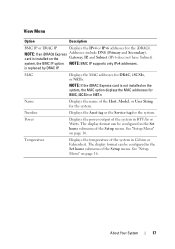
system, the BMC IP option NOTE: BMC IP supports only IPv4 addresses. is not installed on page 16. Power Displays the power output of the system in the Set home submenu of the Setup menu. See "Setup Menu" on the Gateway, IP, and Subnet (IPv6 does not ...
system, the BMC IP option NOTE: BMC IP supports only IPv4 addresses. is not installed on page 16. Power Displays the power output of the system in the Set home submenu of the Setup menu. See "Setup Menu" on the Gateway, IP, and Subnet (IPv6 does not ...

Hardware Owner's Manual
Page 18
Blinks green, amber, and off until all hard drives are not ready for insertion or removal NOTE: The drive status indicator remains off Drive predicted failure 18 About Your System Hard-Drive Indicator Patterns 1 2 1 hard-drive activity indicator (green) 2 hard-drive status indicator (green and amber) Drive-Status Indicator Pattern (RAID Only) Condition Blinks green two times per second Identify drive/preparing for removal Off Drive ready for insertion or removal during this time. Drives are initialized after system power is applied.
Blinks green, amber, and off until all hard drives are not ready for insertion or removal NOTE: The drive status indicator remains off Drive predicted failure 18 About Your System Hard-Drive Indicator Patterns 1 2 1 hard-drive activity indicator (green) 2 hard-drive status indicator (green and amber) Drive-Status Indicator Pattern (RAID Only) Condition Blinks green two times per second Identify drive/preparing for removal Off Drive ready for insertion or removal during this time. Drives are initialized after system power is applied.
Hardware Owner's Manual
Page 20
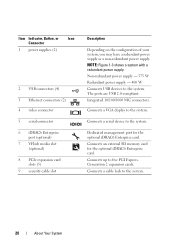
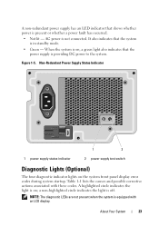
...memory card for the optional iDRAC6 Enterprise card. Connects up to the system. 20 About Your System Item Indicator, Button, or Icon Connector 1 power supplies (2) 2 USB connectors (4) 3 Ethernet connectors (2) 4 video connector 5 serial connector 6 iDRAC6 Enterprise port (optional) 7 VFlash media ...Depending on the configuration of your system, you may have a redundant power supply or a non-redundant power supply. Connects a cable lock to five PCI Express. NOTE: Figure 1-3 shows a system with a redundant power supply. Connects a serial device to the system. Generation 2 expansion...
...memory card for the optional iDRAC6 Enterprise card. Connects up to the system. 20 About Your System Item Indicator, Button, or Icon Connector 1 power supplies (2) 2 USB connectors (4) 3 Ethernet connectors (2) 4 video connector 5 serial connector 6 iDRAC6 Enterprise port (optional) 7 VFlash media ...Depending on the configuration of your system, you may have a redundant power supply or a non-redundant power supply. Connects a cable lock to five PCI Express. NOTE: Figure 1-3 shows a system with a redundant power supply. Connects a serial device to the system. Generation 2 expansion...
Hardware Owner's Manual
Page 21
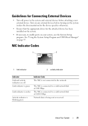
... been installed on the system. • If necessary, to the network. NIC Indicator Codes 1 2 1 link indicator 2 activity indicator Indicator Link and activity indicators are off power to the system and external devices before turning on the system (unless the documentation for the device specifies otherwise). • Ensure that the appropriate driver...
... been installed on the system. • If necessary, to the network. NIC Indicator Codes 1 2 1 link indicator 2 activity indicator Indicator Link and activity indicators are off power to the system and external devices before turning on the system (unless the documentation for the device specifies otherwise). • Ensure that the appropriate driver...

Hardware Owner's Manual
Page 22
... the system is on, a green light indicates that the power supply is providing DC power to the system. • Amber - When hot-adding a power supply, this indicates that the power supply is mismatched with the power supply. • Alternating green and amber - Power Indicator Codes The power supplies have indicators that matches the capacity of the other...
... the system is on, a green light indicates that the power supply is providing DC power to the system. • Amber - When hot-adding a power supply, this indicates that the power supply is mismatched with the power supply. • Alternating green and amber - Power Indicator Codes The power supplies have indicators that matches the capacity of the other...
Hardware Owner's Manual
Page 23
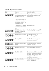
... actions associated with an LCD display. About Your System 23 It also indicates that the power supply is in standby mode. • Green - AC power is present or whether a power fault has occurred. • Not lit - When the system is on the system ...front panel display error codes during system startup. Non-Redundant Power Supply Status Indicator 1 2 1 power supply status indicator 2 power supply test switch Diagnostic Lights (Optional) The four diagnostic indicator lights on , a green light also indicates that the...
... actions associated with an LCD display. About Your System 23 It also indicates that the power supply is in standby mode. • Green - AC power is present or whether a power fault has occurred. • Not lit - When the system is on the system ...front panel display error codes during system startup. Non-Redundant Power Supply Status Indicator 1 2 1 power supply status indicator 2 power supply test switch Diagnostic Lights (Optional) The four diagnostic indicator lights on , a green light also indicates that the...
Hardware Owner's Manual
Page 24
... information on the drives installed in a normal Plug the system into a working off condition or a possible electrical outlet and press the pre-BIOS failure has power button. Diagnostic Indicator Codes Code Causes Corrective Action The system is in your system. Possible video failure.
... information on the drives installed in a normal Plug the system into a working off condition or a possible electrical outlet and press the pre-BIOS failure has power button. Diagnostic Indicator Codes Code Causes Corrective Action The system is in your system. Possible video failure.
Hardware Owner's Manual
Page 26
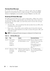
... failure events. Viewing Status Messages If a system error occurs, the LCD screen will lose the event history for the system. • Power cycle - system for approximately ten seconds, reconnect the power cable, and restart the system. See "Troubleshooting System Cooling Problems" on page 177. NOTE: The following LCD status messages are displayed.... LCD Status Messages Code Text Causes Corrective Actions E1000 Failsafe voltage error. E1114 Ambient Temp exceeds allowed range. Check the system event log Remove AC power to view the error.
... failure events. Viewing Status Messages If a system error occurs, the LCD screen will lose the event history for the system. • Power cycle - system for approximately ten seconds, reconnect the power cable, and restart the system. See "Troubleshooting System Cooling Problems" on page 177. NOTE: The following LCD status messages are displayed.... LCD Status Messages Code Text Causes Corrective Actions E1000 Failsafe voltage error. E1114 Ambient Temp exceeds allowed range. Check the system event log Remove AC power to view the error.
Hardware Owner's Manual
Page 27
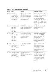
.... Check battery. page 152. E1229 CPU # VCORE Regulator failure. Reseat CPU. Specified processor VCORE voltage regulator has failed. Reseat the processor. About Your System 27 Power cycle AC. Check battery. If the problem persists, see "Getting Help" on page 154. LCD Status Messages (continued) Code Text Causes Corrective Actions E1116 Memory...
.... Check battery. page 152. E1229 CPU # VCORE Regulator failure. Reseat CPU. Specified processor VCORE voltage regulator has failed. Reseat the processor. About Your System 27 Power cycle AC. Check battery. If the problem persists, see "Getting Help" on page 154. LCD Status Messages (continued) Code Text Causes Corrective Actions E1116 Memory...


