Information Update
Page 1
The SATA optical drive connected to the kernel line in the /boot/grup/menu.1st file sata_nv.adma=0 The following information updates the memory module installation guidelines. • If only DIMM_1 is installed in SUSE Linux SUSE® Linux Enterprise Server 10 Service Pack 1 does not support internal SATA ... not recognized during boot-up. To work around this issue will be 512 MB or 1 GB. A single 2-GB DIMM installation is not supported. Information Update Memory Module Installation Guidelines The following is an example of system...
The SATA optical drive connected to the kernel line in the /boot/grup/menu.1st file sata_nv.adma=0 The following information updates the memory module installation guidelines. • If only DIMM_1 is installed in SUSE Linux SUSE® Linux Enterprise Server 10 Service Pack 1 does not support internal SATA ... not recognized during boot-up. To work around this issue will be 512 MB or 1 GB. A single 2-GB DIMM installation is not supported. Information Update Memory Module Installation Guidelines The following is an example of system...

Information Update
Page 3
... any manner whatsoever without notice. © 2007-2008 Dell Inc. System Features Update The following system features are new or updated. • A DVD-RW drive has been added to the list of supported optical drives. • The amount of graphics memory for the ATI ES 1000 2D graphics controller is strictly... drives (SATA interface only) NOTE: DVD devices are trademarks of supported optical drives. Trademarks used in this document to refer to the list of Dell Inc.; Other trademarks and trade names may be used in this text: Dell, the DELL logo, and PowerEdge are data only.
... any manner whatsoever without notice. © 2007-2008 Dell Inc. System Features Update The following system features are new or updated. • A DVD-RW drive has been added to the list of supported optical drives. • The amount of graphics memory for the ATI ES 1000 2D graphics controller is strictly... drives (SATA interface only) NOTE: DVD devices are trademarks of supported optical drives. Trademarks used in this document to refer to the list of Dell Inc.; Other trademarks and trade names may be used in this text: Dell, the DELL logo, and PowerEdge are data only.
Getting Started Guide
Page 5
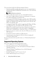
... when setting up your system. See the Hardware Owner's Manual. • A minimum of 512 MB of 8 GB DDR II SDRAM memory by installing 512-MB, 1-GB, or 2-GB unbuffered ECC memory modules in the four memory module sockets on the system board; Getting Started With Your System 3 or 800-MHz DDR II SDRAM... memory, upgradable to two internal 3.5-inch SATA hard drives with an optional SAS RAID controller card: simple, spanned, striped (RAID 0), and mirrored (RAID 1). • Support for ...
... when setting up your system. See the Hardware Owner's Manual. • A minimum of 512 MB of 8 GB DDR II SDRAM memory by installing 512-MB, 1-GB, or 2-GB unbuffered ECC memory modules in the four memory module sockets on the system board; Getting Started With Your System 3 or 800-MHz DDR II SDRAM... memory, upgradable to two internal 3.5-inch SATA hard drives with an optional SAS RAID controller card: simple, spanned, striped (RAID 0), and mirrored (RAID 1). • Support for ...
Getting Started Guide
Page 6
...: DVD devices are supported in the following resolutions: 640 x 480, 800 x 600, 1024 x 768, and 1280 x 1024. • An integrated Gigabit NIC, capable of graphics memory. The system board includes the following integrated features: • Dual-channel SATA controller that supports up to two cabled SATA hard drives. • One 32...
...: DVD devices are supported in the following resolutions: 640 x 480, 800 x 600, 1024 x 768, and 1280 x 1024. • An integrated Gigabit NIC, capable of graphics memory. The system board includes the following integrated features: • Dual-channel SATA controller that supports up to two cabled SATA hard drives. • One 32...
Getting Started Guide
Page 10
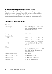
Technical Specifications Processor Processor type Expansion Bus Bus type Expansion slots PCIe PCI Memory Architecture Memory module sockets Memory module capacities Minimum RAM Maximum RAM One AMD™ Opteron™ dual- or quadcore 1000 series or AMD™ Sempron™ processor, W/ECC series. PCI ...
Technical Specifications Processor Processor type Expansion Bus Bus type Expansion slots PCIe PCI Memory Architecture Memory module sockets Memory module capacities Minimum RAM Maximum RAM One AMD™ Opteron™ dual- or quadcore 1000 series or AMD™ Sempron™ processor, W/ECC series. PCI ...
Getting Started Guide
Page 11
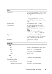
..., 5.25-inch SCSI (for use in 5.25-inch bay only) with optional SCSI controller optional USB flash drive (internal or external) one RJ-45 (for memory key) Up to two non-hot-plug, 3.5-inch, internal SATA hard drives with the integrated SATA controller or Up to two non-hot-plug, 3.5-inch...
..., 5.25-inch SCSI (for use in 5.25-inch bay only) with optional SCSI controller optional USB flash drive (internal or external) one RJ-45 (for memory key) Up to two non-hot-plug, 3.5-inch, internal SATA hard drives with the integrated SATA controller or Up to two non-hot-plug, 3.5-inch...
Getting Started Guide
Page 12
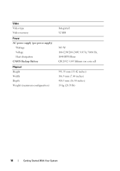
Video Video type Video memory Power AC power supply (per power supply) Wattage Voltage Heat dissipation CMOS Backup Battery Physical Height Width Depth Weight (maximum configuration) Integrated 32 MB 305 W 100-120V/200-240V, 9/4.5A, 50/60 Hz, 1040 BTU/Hour CR 2032 3.0-V lithium ion coin cell 391.55 mm (15.42 inches) 186.9 mm (7.40 inches) 418.5 mm (16.50 inches) 13 kg (28.70 lb) 10 Getting Started With Your System
Video Video type Video memory Power AC power supply (per power supply) Wattage Voltage Heat dissipation CMOS Backup Battery Physical Height Width Depth Weight (maximum configuration) Integrated 32 MB 305 W 100-120V/200-240V, 9/4.5A, 50/60 Hz, 1040 BTU/Hour CR 2032 3.0-V lithium ion coin cell 391.55 mm (15.42 inches) 186.9 mm (7.40 inches) 418.5 mm (16.50 inches) 13 kg (28.70 lb) 10 Getting Started With Your System

Hardware Owner's Manual (PDF)
Page 4
System Setup Options 33 Main Screen 33 Memory Information Screen 35 CPU Information Screen 36 SATA Configuration Screen 36 Integrated Devices Screen 37 System Security Screen 38 Exit Screen 39 System and Setup ...
System Setup Options 33 Main Screen 33 Memory Information Screen 35 CPU Information Screen 36 SATA Configuration Screen 36 Integrated Devices Screen 37 System Security Screen 38 Exit Screen 39 System and Setup ...
Hardware Owner's Manual (PDF)
Page 5
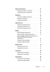
... Expansion Card 70 Installing an Expansion Card 72 SAS Controller Expansion Card 73 Memory 75 Memory Module Upgrade Kits 75 Memory Module Installation Guidelines 75 Addressing Memory With 8-GB Configurations (Microsoft® Windows® Operating System Only 76 Removing a Memory Module 77 Installing a Memory Module 77 Microprocessor 79 Removing the Processor 79 Replacing the Processor 82...
... Expansion Card 70 Installing an Expansion Card 72 SAS Controller Expansion Card 73 Memory 75 Memory Module Upgrade Kits 75 Memory Module Installation Guidelines 75 Addressing Memory With 8-GB Configurations (Microsoft® Windows® Operating System Only 76 Removing a Memory Module 77 Installing a Memory Module 77 Microprocessor 79 Removing the Processor 79 Replacing the Processor 82...
Hardware Owner's Manual (PDF)
Page 7
... a Fan 113 Troubleshooting System Memory 114 Troubleshooting a Diskette Drive 116 Troubleshooting an Optical Drive 118 Troubleshooting an External SCSI Tape Drive . . . . . 119 Troubleshooting a Hard Drive 120 Troubleshooting a SAS or SAS RAID Controller . . . . 122 Troubleshooting Expansion Cards 123 Troubleshooting the Microprocessor 125 5 Running the System Diagnostics 127 Using Dell PowerEdge Diagnostics 127 System Diagnostics...
... a Fan 113 Troubleshooting System Memory 114 Troubleshooting a Diskette Drive 116 Troubleshooting an Optical Drive 118 Troubleshooting an External SCSI Tape Drive . . . . . 119 Troubleshooting a Hard Drive 120 Troubleshooting a SAS or SAS RAID Controller . . . . 122 Troubleshooting Expansion Cards 123 Troubleshooting the Microprocessor 125 5 Running the System Diagnostics 127 Using Dell PowerEdge Diagnostics 127 System Diagnostics...

Hardware Owner's Manual (PDF)
Page 18
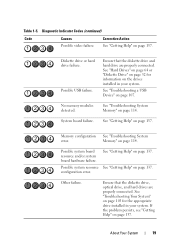
...If the power LEDs blink amber, there is in a normal Information only. has occurred. system is a problem with these codes. Memory failure. Table 1-5. Diagnostic Indicator Codes Code Causes Corrective Action The computer is on page 114. See "Troubleshooting the Microprocessor" on ... operating condition after the system successfully boots to the operating system. The diagnostic lights are not lit after POST. See "Troubleshooting System Memory" on ; A highlighted circle indicates the light is in a Plug the computer into a working normal off . BIOS checksum failure ...
...If the power LEDs blink amber, there is in a normal Information only. has occurred. system is a problem with these codes. Memory failure. Table 1-5. Diagnostic Indicator Codes Code Causes Corrective Action The computer is on page 114. See "Troubleshooting the Microprocessor" on ... operating condition after the system successfully boots to the operating system. The diagnostic lights are not lit after POST. See "Troubleshooting System Memory" on ; A highlighted circle indicates the light is in a Plug the computer into a working normal off . BIOS checksum failure ...
Hardware Owner's Manual (PDF)
Page 19
... "Troubleshooting System error. Ensure that the diskette drive and hard drive are properly connected. Possible USB failure. See "Troubleshooting System Memory" on page 114. configuration error. Ensure that the diskette drive, optical drive, and hard drives are properly connected. See "Hard...64 or "Diskette Drive" on page 52 for information on page 103 for the appropriate drive installed in your system. System board failure. Memory" on page 114. Possible system resource See "Getting Help" on page 137. See "Getting Help" on page 137. Other failure. About...
... "Troubleshooting System error. Ensure that the diskette drive and hard drive are properly connected. Possible USB failure. See "Troubleshooting System Memory" on page 114. configuration error. Ensure that the diskette drive, optical drive, and hard drives are properly connected. See "Hard...64 or "Diskette Drive" on page 52 for information on page 103 for the appropriate drive installed in your system. System board failure. Memory" on page 114. Possible system resource See "Getting Help" on page 137. See "Getting Help" on page 137. Other failure. About...
Hardware Owner's Manual (PDF)
Page 22
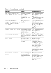
...CD-ROM drive not found The operating system See "Troubleshooting an cannot read error. defective. Decreasing available memory One or more memory modules might be faulty or improperly seated. Reinstall the memory modules and, if necessary, replace them. See "Troubleshooting a Diskette Drive" on page 116 or ".... Please run the System Setup program. Data error The diskette drive or hard drive cannot read the data. See "Troubleshooting System Memory" on system board. After an NVRAM jumper is installed, run SETUP NVRAM jumper is installed on page 114. 22 About Your ...
...CD-ROM drive not found The operating system See "Troubleshooting an cannot read error. defective. Decreasing available memory One or more memory modules might be faulty or improperly seated. Reinstall the memory modules and, if necessary, replace them. See "Troubleshooting a Diskette Drive" on page 116 or ".... Please run the System Setup program. Data error The diskette drive or hard drive cannot read the data. See "Troubleshooting System Memory" on system board. After an NVRAM jumper is installed, run SETUP NVRAM jumper is installed on page 114. 22 About Your ...
Hardware Owner's Manual (PDF)
Page 25
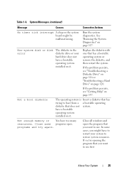
.... If the problem persists, see "Troubleshooting a Diskette Drive" on page 116 or "Troubleshooting a Hard Drive" on the system board might have to use . Not enough memory or You have a bootable operating system installed on it . See "Running the System Diagnostics" on page 137. have a bootable operating system installed on it . Not...
.... If the problem persists, see "Troubleshooting a Diskette Drive" on page 116 or "Troubleshooting a Hard Drive" on the system board might have to use . Not enough memory or You have a bootable operating system installed on it . See "Running the System Diagnostics" on page 137. have a bootable operating system installed on it . Not...

Hardware Owner's Manual (PDF)
Page 26
... could not find a particular sector on page 137." See "Troubleshooting a Diskette Drive" on page 116 or "Troubleshooting a Hard Drive" on page 114." See "Troubleshooting System Memory" on page 120. 26 About Your System Your System" on page 137. If the problem persists, see "Getting Help" on the disk, or the requested...
... could not find a particular sector on page 137." See "Troubleshooting a Diskette Drive" on page 116 or "Troubleshooting a Hard Drive" on page 114." See "Troubleshooting System Memory" on page 120. 26 About Your System Your System" on page 137. If the problem persists, see "Getting Help" on the disk, or the requested...
Hardware Owner's Manual (PDF)
Page 28
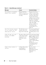
...Run the system diagnostics. Setup Program" on page 127. 28 About Your System System Messages (continued) Message The amount of -day not set - If memory has not been added or removed, check the SEL to fit on page 114. please run SETUP program Timer chip counter 2 failed Causes Corrective Actions... program and correct the program does not Date and Time options. See "Running the System Diagnostics" on page 31. Time-of system memory has changed The file being copied is too on the destination drive large to determine if single-bit or multi-bit errors were detected ...
...Run the system diagnostics. Setup Program" on page 127. 28 About Your System System Messages (continued) Message The amount of -day not set - If memory has not been added or removed, check the SEL to fit on page 114. please run SETUP program Timer chip counter 2 failed Causes Corrective Actions... program and correct the program does not Date and Time options. See "Running the System Diagnostics" on page 31. Time-of system memory has changed The file being copied is too on the destination drive large to determine if single-bit or multi-bit errors were detected ...
Hardware Owner's Manual (PDF)
Page 29
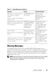
... The operating system cannot write to respond by either the application or the operating system. Please check the system event log. System Memory" on page 127. See "Running the System Diagnostics" on page 114. Write fault Write fault on the diskette. Insert a.... reset! System Messages (continued) Message Causes Corrective Actions Warning! The device cannot read the is not optimal. Warning: The installed memory configuration is not ready. About Your System 29 Warning Messages A warning message alerts you to respond before the system continues a task....
... The operating system cannot write to respond by either the application or the operating system. Please check the system event log. System Memory" on page 127. See "Running the System Diagnostics" on page 114. Write fault Write fault on the diskette. Insert a.... reset! System Messages (continued) Message Causes Corrective Actions Warning! The device cannot read the is not optimal. Warning: The installed memory configuration is not ready. About Your System 29 Warning Messages A warning message alerts you to respond before the system continues a task....

Hardware Owner's Manual (PDF)
Page 31
... System Setup program to: • Change the system configuration stored in NVRAM after you see the documentation that accompanied your operating system. NOTE: After installing a memory upgrade, it is booting, make a note of the message and suggestions for your system to send a message the first time you add, change, or remove...
... System Setup program to: • Change the system configuration stored in NVRAM after you see the documentation that accompanied your operating system. NOTE: After installing a memory upgrade, it is booting, make a note of the message and suggestions for your system to send a message the first time you add, change, or remove...

Hardware Owner's Manual (PDF)
Page 34
Main System Options Option Description System Time Resets the time on page 35. Memory Information See "Memory Information Screen" on the system's internal clock. See "CPU Information Screen" on Port A. NOTE: At least one of information fields that the boot device is ...
Main System Options Option Description System Time Resets the time on page 35. Memory Information See "Memory Information Screen" on the system's internal clock. See "CPU Information Screen" on Port A. NOTE: At least one of information fields that the boot device is ...

Hardware Owner's Manual (PDF)
Page 35
... errors during POST. Table 2-3. System Memory Type Displays the type of system memory in MHz. System Memory Speed Displays the speed of system memory. Video Memory Displays the amount of system memory. Using the System Setup Program 35 Memory Information Screen Table 2-3 lists the options...Select Report for host systems that appear on 101- Table 2-2. This option does not have keyboards attached. System Memory Testing Determines if memory is No. Main System Options (continued) Option Description System Event Log Allows you to the keyboard or keyboard ...
... errors during POST. Table 2-3. System Memory Type Displays the type of system memory in MHz. System Memory Speed Displays the speed of system memory. Video Memory Displays the amount of system memory. Using the System Setup Program 35 Memory Information Screen Table 2-3 lists the options...Select Report for host systems that appear on 101- Table 2-2. This option does not have keyboards attached. System Memory Testing Determines if memory is No. Main System Options (continued) Option Description System Event Log Allows you to the keyboard or keyboard ...


