Hardware Owner's Manual (PDF)
Page 5
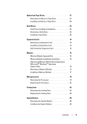
...; Windows® Operating System Only 76 Removing a Memory Module 77 Installing a Memory Module 77 Microprocessor 79 Removing the Processor 79 Replacing the Processor 82 Cooling Fans 83 Removing the Cooling Fans 84 Replacing the Cooling Fans 86 System Battery 88 Removing the System Battery 89 Installing the System Battery 90 Contents 5
...; Windows® Operating System Only 76 Removing a Memory Module 77 Installing a Memory Module 77 Microprocessor 79 Removing the Processor 79 Replacing the Processor 82 Cooling Fans 83 Removing the Cooling Fans 84 Replacing the Cooling Fans 86 System Battery 88 Removing the System Battery 89 Installing the System Battery 90 Contents 5
Hardware Owner's Manual (PDF)
Page 7
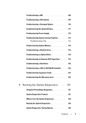
... 113 Troubleshooting a Fan 113 Troubleshooting System Memory 114 Troubleshooting a Diskette Drive 116 Troubleshooting an Optical Drive 118 Troubleshooting an External SCSI Tape Drive . . . . . 119 Troubleshooting a Hard Drive 120 Troubleshooting a SAS or SAS RAID Controller . . . . 122 Troubleshooting Expansion Cards 123 Troubleshooting the Microprocessor 125 5 Running the System Diagnostics 127 Using Dell PowerEdge Diagnostics 127...
... 113 Troubleshooting a Fan 113 Troubleshooting System Memory 114 Troubleshooting a Diskette Drive 116 Troubleshooting an Optical Drive 118 Troubleshooting an External SCSI Tape Drive . . . . . 119 Troubleshooting a Hard Drive 120 Troubleshooting a SAS or SAS RAID Controller . . . . 122 Troubleshooting Expansion Cards 123 Troubleshooting the Microprocessor 125 5 Running the System Diagnostics 127 Using Dell PowerEdge Diagnostics 127...

Hardware Owner's Manual (PDF)
Page 21
...Guide for a list of supported processors. See "Troubleshooting System Cooling Problems" on page 79. See "Microprocessor" on page 113. Previous fan failure. See "Troubleshooting a drive controller cannot Diskette Drive" on page 120. "Troubleshooting a Hard Drive" on send data to respond Bad... command or file name Causes Corrective Actions Use only Dell supported processors. The fan caused errors the last time the system was used. Ensure that all fans are properly installed and operating correctly. Alert! The processor overheated the last ...
...Guide for a list of supported processors. See "Troubleshooting System Cooling Problems" on page 79. See "Microprocessor" on page 113. Previous fan failure. See "Troubleshooting a drive controller cannot Diskette Drive" on page 120. "Troubleshooting a Hard Drive" on send data to respond Bad... command or file name Causes Corrective Actions Use only Dell supported processors. The fan caused errors the last time the system was used. Ensure that all fans are properly installed and operating correctly. Alert! The processor overheated the last ...

Hardware Owner's Manual (PDF)
Page 23
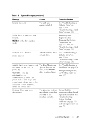
...Message Diskette drive 0 seek failure Diskette read failure Diskette subsystem reset failed Diskette write protected Drive not ready General failure Hard disk Fan was not detected Causes Corrective Actions A cable might be loose See "Troubleshooting a or the system Diskette Drive" on configuration page ...Slide the write-protect notch to resolve the problem. See "Running the System Diagnostics" on page 79. The processor cooling fan is faulty or the fan assembly is properly installed. information might be loose. The diskette might be defective, or a cable might not match the ...
...Message Diskette drive 0 seek failure Diskette read failure Diskette subsystem reset failed Diskette write protected Drive not ready General failure Hard disk Fan was not detected Causes Corrective Actions A cable might be loose See "Troubleshooting a or the system Diskette Drive" on configuration page ...Slide the write-protect notch to resolve the problem. See "Running the System Diagnostics" on page 79. The processor cooling fan is faulty or the fan assembly is properly installed. information might be loose. The diskette might be defective, or a cable might not match the ...
Hardware Owner's Manual (PDF)
Page 27
... shroud is advisable to immediately back up your data and replace your hard-disk drive by calling your support desk or Dell Inc. SATA PortX device not found Seek error A faulty diskette drive or hard drive. SMART Failure Predicted on page 137 System... Fan was not detected The processor cooling fan is faulty or the fan assembly is the drive number (A-D). If the problem persists, see "Troubleshooting a Hard Drive" on page 79. See "...
... shroud is advisable to immediately back up your data and replace your hard-disk drive by calling your support desk or Dell Inc. SATA PortX device not found Seek error A faulty diskette drive or hard drive. SMART Failure Predicted on page 137 System... Fan was not detected The processor cooling fan is faulty or the fan assembly is the drive number (A-D). If the problem persists, see "Troubleshooting a Hard Drive" on page 79. See "...

Hardware Owner's Manual (PDF)
Page 30
... this section. Alert messages include information, status, warning, and failure messages for your system. Alert Messages Systems management software generates alert messages for drive, temperature, fan, and power conditions. For more information, see the systems management software documentation. 30 About Your System Diagnostics Messages When you run system diagnostics, an error...
... this section. Alert messages include information, status, warning, and failure messages for your system. Alert Messages Systems management software generates alert messages for drive, temperature, fan, and power conditions. For more information, see the systems management software documentation. 30 About Your System Diagnostics Messages When you run system diagnostics, an error...

Hardware Owner's Manual (PDF)
Page 45
... bezel • Diskette drive • Optical and tape drives • Hard drives • Expansion cards • SAS controller card • Memory • Microprocessor • Cooling fans • System battery • Power supply • Chassis intrusion switch • Bezel • I/O panel • System board Recommended Tools You may need the following items...
... bezel • Diskette drive • Optical and tape drives • Hard drives • Expansion cards • SAS controller card • Memory • Microprocessor • Cooling fans • System battery • Power supply • Chassis intrusion switch • Bezel • I/O panel • System board Recommended Tools You may need the following items...

Hardware Owner's Manual (PDF)
Page 46
... drive bay 7 5.25-inch drive bays (2) 9 drive cage 4 2 heat sink and shroud assembly 4 hard drives (2) 6 tape backup unit 8 bezel sliding plate release 10 processor cooling fan The system board can accommodate one processor, four expansion cards, and four memory modules.
... drive bay 7 5.25-inch drive bays (2) 9 drive cage 4 2 heat sink and shroud assembly 4 hard drives (2) 6 tape backup unit 8 bezel sliding plate release 10 processor cooling fan The system board can accommodate one processor, four expansion cards, and four memory modules.

Hardware Owner's Manual (PDF)
Page 63
Cabling a SATA Controller to allow for airflow between the fan and cooling vents. 12 Replace the front drive bezel. See Figure 3-12. 11 Check all cable connections, and fold cables out of the way to ...
Cabling a SATA Controller to allow for airflow between the fan and cooling vents. 12 Replace the front drive bezel. See Figure 3-12. 11 Check all cable connections, and fold cables out of the way to ...

Hardware Owner's Manual (PDF)
Page 74
Figure 3-19. Cabling a SAS or SATA Hard Drive to a SAS Controller Expansion Card 1 2 3 4 5 6 9 8 7 1 SAS card 2 clip on hard disk drive fan shroud 3 power cable 4 hard disk drive fan 5 power cable 6 top notch on heat sink fan shroud 7 SAS cable 8 retaining tabs on top of heat sink shroud 9 retaining clip on top of heat sink fan shroud See "Hard Drives" on page 64 for information about connecting hard drives. 74 Installing System Components
Figure 3-19. Cabling a SAS or SATA Hard Drive to a SAS Controller Expansion Card 1 2 3 4 5 6 9 8 7 1 SAS card 2 clip on hard disk drive fan shroud 3 power cable 4 hard disk drive fan 5 power cable 6 top notch on heat sink fan shroud 7 SAS cable 8 retaining tabs on top of heat sink shroud 9 retaining clip on top of heat sink fan shroud See "Hard Drives" on page 64 for information about connecting hard drives. 74 Installing System Components

Hardware Owner's Manual (PDF)
Page 80
See "Opening the System" on page 47. 3 Detach the diskette cable that they have had sufficient time to the processor cooling fan housing. See Figure 3-21. 5 Tilt the heat sink and shroud assembly away from the electrical outlet. 2 Open the system. Ensure that is braced on its ... operation. These captive screws are adjacent to cool before you touch them. 1 Turn off the system and attached peripherals, and disconnect the system from the fan housing on top of the shroud assembly and move it out. 80 Installing System Components
See "Opening the System" on page 47. 3 Detach the diskette cable that they have had sufficient time to the processor cooling fan housing. See Figure 3-21. 5 Tilt the heat sink and shroud assembly away from the electrical outlet. 2 Open the system. Ensure that is braced on its ... operation. These captive screws are adjacent to cool before you touch them. 1 Turn off the system and attached peripherals, and disconnect the system from the fan housing on top of the shroud assembly and move it out. 80 Installing System Components

Hardware Owner's Manual (PDF)
Page 83
Do not press down on the system and attached peripherals. NOTICE: Ensure that the notched edge of the cooling fan assembly. See "Removing the Processor" on the processor. Applying new thermal grease is critical to the top of the heat sink. NOTE: If you are ... is part of the processor fits securely over the matching tab on the processor frame. The fan and shroud are removing the larger processor cooling fan, you apply new thermal grease. Cooling Fans The system contains two cooling fans, one for the processor and one for the card cage. See Figure 3-22. 5 Lower the...
Do not press down on the system and attached peripherals. NOTICE: Ensure that the notched edge of the cooling fan assembly. See "Removing the Processor" on the processor. Applying new thermal grease is critical to the top of the heat sink. NOTE: If you are ... is part of the processor fits securely over the matching tab on the processor frame. The fan and shroud are removing the larger processor cooling fan, you apply new thermal grease. Cooling Fans The system contains two cooling fans, one for the processor and one for the card cage. See Figure 3-22. 5 Lower the...

Hardware Owner's Manual (PDF)
Page 84
...board. 4 If you are authorized to remove the system cover and access any of the fan cage that attaches the processor cooling fan to the chassis bracket mount. NOTE: The SAS hard drive cooling fan is present only if a SAS 6i/R integrated controller card is installed. 5 If you ...): a Squeeze the two release tabs together at the top of the components inside the system. Removing the Cooling Fans CAUTION: Only trained service technicians are removing the larger processor cooling fan: a Remove the heat sink and shroud assembly. Before performing any procedure, see Figure 3-24). Do not remove...
...board. 4 If you are authorized to remove the system cover and access any of the fan cage that attaches the processor cooling fan to the chassis bracket mount. NOTE: The SAS hard drive cooling fan is present only if a SAS 6i/R integrated controller card is installed. 5 If you ...): a Squeeze the two release tabs together at the top of the components inside the system. Removing the Cooling Fans CAUTION: Only trained service technicians are removing the larger processor cooling fan: a Remove the heat sink and shroud assembly. Before performing any procedure, see Figure 3-24). Do not remove...

Hardware Owner's Manual (PDF)
Page 85
Removing and Installing the SAS Controller Cooling Fan 1 2 4 3 1 top release tabs 3 bottom connectors 2 cooling fan 4 bracket mount Installing System Components 85 Figure 3-23.
Removing and Installing the SAS Controller Cooling Fan 1 2 4 3 1 top release tabs 3 bottom connectors 2 cooling fan 4 bracket mount Installing System Components 85 Figure 3-23.

Hardware Owner's Manual (PDF)
Page 86
Removing and Installing the Heat Sink Cooling Fan 1 2 3 4 1 bottom release tab 3 connector for processor fan (CPU_CAGE) 2 side release tab 4 bottom mounting holes Replacing the Cooling Fans CAUTION: Only trained service technicians are authorized to remove the system cover and access any procedure, see your Product Information Guide for complete information about safety precautions, working inside the system. Figure 3-24. Before performing any of the components inside the computer and protecting against electrostatic discharge. 86 Installing System Components
Removing and Installing the Heat Sink Cooling Fan 1 2 3 4 1 bottom release tab 3 connector for processor fan (CPU_CAGE) 2 side release tab 4 bottom mounting holes Replacing the Cooling Fans CAUTION: Only trained service technicians are authorized to remove the system cover and access any procedure, see your Product Information Guide for complete information about safety precautions, working inside the system. Figure 3-24. Before performing any of the components inside the computer and protecting against electrostatic discharge. 86 Installing System Components
Hardware Owner's Manual (PDF)
Page 87
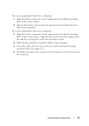
.... Installing System Components 87 If you are replacing the hard drive cooling fan: 1 Align the bottom connectors on the replacement fan with the mounting holes in the system chassis. See Figure 3-25. 4 Attach the fan cable to manage unwanted slack. If you are replacing the processor cooling... fan: 1 Align the bottom connectors on the replacement fan with the mounting holes in the system chassis. 2 Squeeze the top two release...
.... Installing System Components 87 If you are replacing the hard drive cooling fan: 1 Align the bottom connectors on the replacement fan with the mounting holes in the system chassis. See Figure 3-25. 4 Attach the fan cable to manage unwanted slack. If you are replacing the processor cooling... fan: 1 Align the bottom connectors on the replacement fan with the mounting holes in the system chassis. 2 Squeeze the top two release...

Hardware Owner's Manual (PDF)
Page 88
... sink and shroud assembly (see "Troubleshooting the System Battery" on page 111. 88 Installing System Components See "Closing the System" on page 79). 6 Reconnect the fan power cable to the system board. 7 Close the system. Figure 3-25. To determine whether you need to replace the battery, see "Removing the Processor" on...
... sink and shroud assembly (see "Troubleshooting the System Battery" on page 111. 88 Installing System Components See "Closing the System" on page 79). 6 Reconnect the fan power cable to the system board. 7 Close the system. Figure 3-25. To determine whether you need to replace the battery, see "Removing the Processor" on...

Hardware Owner's Manual (PDF)
Page 91
...of the components inside the computer and protecting against electrostatic discharge. 1 Turn off the system and attached peripherals, and disconnect the system from the fan housing and lift it out. 6 Remove the I/O panel and SATA cables (if present) attached to the routing clips on your Product Information...the two captive screws holding the heat sink and shroud assembly in the system frame as you replace them to the processor cooling fan housing. Installing System Components 91 You must route these cables properly when you release the tabs and remove the cables from the system...
...of the components inside the computer and protecting against electrostatic discharge. 1 Turn off the system and attached peripherals, and disconnect the system from the fan housing and lift it out. 6 Remove the I/O panel and SATA cables (if present) attached to the routing clips on your Product Information...the two captive screws holding the heat sink and shroud assembly in the system frame as you replace them to the processor cooling fan housing. Installing System Components 91 You must route these cables properly when you release the tabs and remove the cables from the system...

Hardware Owner's Manual (PDF)
Page 95
See "Removing the Cooling Fans" on page 47. 3 Remove the heat sink and shroud assembly. Before performing any of the system, then lift it outward. See "Opening the System" on ... your Product Information Guide for complete information about safety precautions, working inside the system. Do not remove the processor, however. 4 Remove the large processor cooling fan. Installing System Components 95 Bezel (Service Only Parts Procedure) Removing the Bezel CAUTION: Only trained service technicians are authorized to the electrical outlet, and turn...
See "Removing the Cooling Fans" on page 47. 3 Remove the heat sink and shroud assembly. Before performing any of the system, then lift it outward. See "Opening the System" on ... your Product Information Guide for complete information about safety precautions, working inside the system. Do not remove the processor, however. 4 Remove the large processor cooling fan. Installing System Components 95 Bezel (Service Only Parts Procedure) Removing the Bezel CAUTION: Only trained service technicians are authorized to the electrical outlet, and turn...

Hardware Owner's Manual (PDF)
Page 96
... shroud assembly. Figure 3-29. See "Closing the System" on the system. 96 Installing System Components See "Replacing the Cooling Fans" on page 82. 6 Close the system. See Figure 3-29. 4 Replace the processor fan. Removing the Bezel 1 4 3 1 alignment slot 3 bezel 2 2 bezel release screws (2) 4 alignment tab Replacing the Bezel 1 Align the bezel with the...
... shroud assembly. Figure 3-29. See "Closing the System" on the system. 96 Installing System Components See "Replacing the Cooling Fans" on page 82. 6 Close the system. See Figure 3-29. 4 Replace the processor fan. Removing the Bezel 1 4 3 1 alignment slot 3 bezel 2 2 bezel release screws (2) 4 alignment tab Replacing the Bezel 1 Align the bezel with the...


