
Information Update
Page 1
... a second processor is used. When performing this procedure, note the following DIMM failed to ensure compatibility. Dell™ PowerEdge™ SC 1430 Systems Information Update Installing a Fourth Hard Drive A fourth hard drive requires an optional hard-drive carrier with a cooling fan. See "System Messages" in your Dell sales agent to train: DIMM x Causes Faulty or improperly installed memory module.
... a second processor is used. When performing this procedure, note the following DIMM failed to ensure compatibility. Dell™ PowerEdge™ SC 1430 Systems Information Update Installing a Fourth Hard Drive A fourth hard drive requires an optional hard-drive carrier with a cooling fan. See "System Messages" in your Dell sales agent to train: DIMM x Causes Faulty or improperly installed memory module.

Getting Started Guide
Page 5
To take advantage of this feature, you must order the microprocessor upgrade kits from Dell contains the correct version of the microprocessor. The upgrade kit from Dell. A fourth hard drive may be installed in features: • Dual-channel IDE controller that supports up to two of the following supported IDE devices: CD, DVD, combination CD...
To take advantage of this feature, you must order the microprocessor upgrade kits from Dell contains the correct version of the microprocessor. The upgrade kit from Dell. A fourth hard drive may be installed in features: • Dual-channel IDE controller that supports up to two of the following supported IDE devices: CD, DVD, combination CD...

Getting Started Guide
Page 11
...-height, 5.25-inch SCSI or IDE (for information on hard drive cooling requirements. one optional 3.5-inch, 1.44-MB external optional USB 3.5-inch, 1.44-MB up to install a fourth hard drive, see the Dell Support website at support.dell.com for use in the flex bay, you decide to four... 3.5-inch internal SAS or SATA drives using one or two SATA drives using internal hard drive bays and controller expansion card -
...-height, 5.25-inch SCSI or IDE (for information on hard drive cooling requirements. one optional 3.5-inch, 1.44-MB external optional USB 3.5-inch, 1.44-MB up to install a fourth hard drive, see the Dell Support website at support.dell.com for use in the flex bay, you decide to four... 3.5-inch internal SAS or SATA drives using one or two SATA drives using internal hard drive bays and controller expansion card -

Hardware Owner's Manual
Page 4
... Replacing the Front Drive Bezel Insert 47 Hard Drives 48 Hard Drive Installation Guidelines 48 Removing a Hard Drive from the Rotatable Carrier 49 Installing a Hard Drive in the Rotatable Carrier 50 Removing an Optional Third Hard Drive 54 Installing an Optional Third Hard Drive 55 Removing an Optional Fourth Hard Drive 58 Installing an Optional Fourth Hard Drive 59 Diskette Drive 63 Removing the Diskette Drive 63 Installing a Diskette...
... Replacing the Front Drive Bezel Insert 47 Hard Drives 48 Hard Drive Installation Guidelines 48 Removing a Hard Drive from the Rotatable Carrier 49 Installing a Hard Drive in the Rotatable Carrier 50 Removing an Optional Third Hard Drive 54 Installing an Optional Third Hard Drive 55 Removing an Optional Fourth Hard Drive 58 Installing an Optional Fourth Hard Drive 59 Diskette Drive 63 Removing the Diskette Drive 63 Installing a Diskette...

Hardware Owner's Manual
Page 5
... Installing the Power Supply 82 Replacing the Cooling Fans 83 Replacing the Card and Front Fans 83 Replacing the Memory Fan 85 Replacing the Fourth Hard-Drive Fan 86 Chassis Intrusion Switch 86 Removing the Chassis Intrusion Switch 86 Installing the Chassis Intrusion Switch 87 Removing and Replacing the Bezel (Service Only...
... Installing the Power Supply 82 Replacing the Cooling Fans 83 Replacing the Card and Front Fans 83 Replacing the Memory Fan 85 Replacing the Fourth Hard-Drive Fan 86 Chassis Intrusion Switch 86 Removing the Chassis Intrusion Switch 86 Installing the Chassis Intrusion Switch 87 Removing and Replacing the Bezel (Service Only...

Hardware Owner's Manual
Page 6
... Cooling Problems 102 Troubleshooting a Fan 103 Troubleshooting System Memory 103 Troubleshooting a Diskette Drive 105 Troubleshooting an Optical Drive 106 Troubleshooting a Hard Drive 107 Troubleshooting a SAS RAID Controller 108 Troubleshooting Expansion Cards 109 Troubleshooting the Microprocessors 110 5 Running the System Diagnostics 113 Using Dell PowerEdge Diagnostics 113 System Diagnostics Features 113 When to Use the System Diagnostics...
... Cooling Problems 102 Troubleshooting a Fan 103 Troubleshooting System Memory 103 Troubleshooting a Diskette Drive 105 Troubleshooting an Optical Drive 106 Troubleshooting a Hard Drive 107 Troubleshooting a SAS RAID Controller 108 Troubleshooting Expansion Cards 109 Troubleshooting the Microprocessors 110 5 Running the System Diagnostics 113 Using Dell PowerEdge Diagnostics 113 System Diagnostics Features 113 When to Use the System Diagnostics...

Hardware Owner's Manual
Page 11
... on the system's front panel. Holds a diskette drive or an optional third hard drive. About Your System 11 Figure 1-1. Front-Panel Features and Indicators 1 2 9 3 8 4 5 7 6 Table 1-2. Indicates hard drive activity. Front-Panel Components Item Component Icon 1 upper 5.25-inch drive bay 2 lower 5.25-inch drive bay 3 flex bay 4 hard-drive activity indicator Description Holds an optical drive. Table 1-2 provides component descriptions.
... on the system's front panel. Holds a diskette drive or an optional third hard drive. About Your System 11 Figure 1-1. Front-Panel Features and Indicators 1 2 9 3 8 4 5 7 6 Table 1-2. Indicates hard drive activity. Front-Panel Components Item Component Icon 1 upper 5.25-inch drive bay 2 lower 5.25-inch drive bay 3 flex bay 4 hard-drive activity indicator Description Holds an optical drive. Table 1-2 provides component descriptions.

Hardware Owner's Manual
Page 12
...on page 15. 12 About Your System Blinking amber - Steady green - Check the diagnostic indicators to be replaced. • If the hard-drive indicator is on . Lights when the system is probably good. No light - The system is off , the power supply may need... Check the diagnostic indicators to the system. See "Diagnostics Indicator Codes" on page 15. The system is powering up. • If the hard-drive indicator is pressed. Steady amber - Table 1-2. Front-Panel Components (continued) Item Component Icon 5 USB connectors (2) Description Connects USB 2.0-compliant devices...
...on page 15. 12 About Your System Blinking amber - Steady green - Check the diagnostic indicators to be replaced. • If the hard-drive indicator is on . Lights when the system is probably good. No light - The system is off , the power supply may need... Check the diagnostic indicators to the system. See "Diagnostics Indicator Codes" on page 15. The system is powering up. • If the hard-drive indicator is pressed. Steady amber - Table 1-2. Front-Panel Components (continued) Item Component Icon 5 USB connectors (2) Description Connects USB 2.0-compliant devices...

Hardware Owner's Manual
Page 16
... If the problem persists, see "Getting Help" on page 123. 16 About Your System Memory failure. Possible video failure. Diskette drive or hard drive failure. No memory modules detected. See "Getting Help" on page 123. system is in your system. See "Troubleshooting Expansion Cards...See "Troubleshooting Your System" on page 110. See "Getting Help" on page 103. See "Hard Drives" on page 48 and "Diskette Drive" on page 63 for information on the drives installed in recovery properly. Possible processor failure. See "Troubleshooting System Memory" on page 123. Ensure...
... If the problem persists, see "Getting Help" on page 123. 16 About Your System Memory failure. Possible video failure. Diskette drive or hard drive failure. No memory modules detected. See "Getting Help" on page 123. system is in your system. See "Troubleshooting Expansion Cards...See "Troubleshooting Your System" on page 110. See "Getting Help" on page 103. See "Hard Drives" on page 48 and "Diskette Drive" on page 63 for information on the drives installed in recovery properly. Possible processor failure. See "Troubleshooting System Memory" on page 123. Ensure...
Hardware Owner's Manual
Page 17
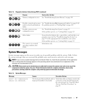
...System Messages Message Alert! See "Front I /O panel and the system board. Table 1-6 lists the system messages that the diskette drive, optical drive, and hard drives are firmly seated in your Product Information Guide for each message. Ensure that can occur and the probable cause and corrective action for ...persists, see "Getting Help" on page 89. The system is in Table 1-6, check the documentation for the appropriate drive installed in the improperly installed or has failed. Diagnostic Indicator Codes During POST (continued) Code Causes Memory configuration error.
...System Messages Message Alert! See "Front I /O panel and the system board. Table 1-6 lists the system messages that the diskette drive, optical drive, and hard drives are firmly seated in your Product Information Guide for each message. Ensure that can occur and the probable cause and corrective action for ...persists, see "Getting Help" on page 89. The system is in Table 1-6, check the documentation for the appropriate drive installed in the improperly installed or has failed. Diagnostic Indicator Codes During POST (continued) Code Causes Memory configuration error.

Hardware Owner's Manual
Page 18
...page 27. Alert! Previous FAN_FRONT failure. Previous FAN_HDD failure. To reset, enter the System Setup program. hard-drive fan for optional fourth hard drive • FAN_MEM - Table 1-6. FAN_PSU was not detected. Alert! Previous FAN_MEM failure. The power supply... last system Information only. System Messages (continued) Message Alert! Alert! Alert! front fan • FAN_HDD - hard-drive fan for optional fourth hard drive • FAN_MEM - The system cover has been opened. card fan • FAN_FRONT - Previous FAN_PSU failure. ...
...page 27. Alert! Previous FAN_FRONT failure. Previous FAN_HDD failure. To reset, enter the System Setup program. hard-drive fan for optional fourth hard drive • FAN_MEM - Table 1-6. FAN_PSU was not detected. Alert! Previous FAN_MEM failure. The power supply... last system Information only. System Messages (continued) Message Alert! Alert! Alert! front fan • FAN_HDD - hard-drive fan for optional fourth hard drive • FAN_MEM - The system cover has been opened. card fan • FAN_FRONT - Previous FAN_PSU failure. ...

Hardware Owner's Manual
Page 22
... Reseat the PCIe card in the specified slot. If the problem persists, see "Troubleshooting a Diskette Drive" on page 105, "Troubleshooting an Optical Drive" on page 106, and "Troubleshooting a Hard Drive" on page 70. Faulty or improperly installed PCIe card in the specified slot number. Table 1-6. Check...Cards" on page 107. Faulty system board. Use a bootable diskette. Reseat the PCIe card in the System Setup program. See your hard drive. Faulty or improperly installed PCIe card in the specified slot. If the problem persists, see "Getting Help" on page 27 for ...
... Reseat the PCIe card in the specified slot. If the problem persists, see "Troubleshooting a Diskette Drive" on page 105, "Troubleshooting an Optical Drive" on page 106, and "Troubleshooting a Hard Drive" on page 70. Faulty or improperly installed PCIe card in the specified slot number. Table 1-6. Check...Cards" on page 107. Faulty system board. Use a bootable diskette. Reseat the PCIe card in the System Setup program. See your hard drive. Faulty or improperly installed PCIe card in the specified slot. If the problem persists, see "Getting Help" on page 27 for ...
Hardware Owner's Manual
Page 23
... 107. Expansion Cards" on page 109. Ensure that faulty. See "Troubleshooting a Diskette Drive" on page 105 or "Troubleshooting a Hard Drive" on page 107 for the appropriate drive(s) installed in your system. About Your System 23 Ensure that checksum failure is defective. ...persists, see "Troubleshooting expansion card. See "Troubleshooting a USB Device" on page 99, "Troubleshooting a Diskette Drive" on page 105, or "Troubleshooting a Hard Drive" on the disk, or the requested sector is detected during all appropriate cables are properly connected. faulty ...
... 107. Expansion Cards" on page 109. Ensure that faulty. See "Troubleshooting a Diskette Drive" on page 105 or "Troubleshooting a Hard Drive" on page 107 for the appropriate drive(s) installed in your system. About Your System 23 Ensure that checksum failure is defective. ...persists, see "Troubleshooting expansion card. See "Troubleshooting a USB Device" on page 99, "Troubleshooting a Diskette Drive" on page 105, or "Troubleshooting a Hard Drive" on the disk, or the requested sector is detected during all appropriate cables are properly connected. faulty ...

Hardware Owner's Manual
Page 24
... not available The key was pressed during POST, but no utility partition exists on the boot hard drive. Dell recommends purchasing memory upgrade kits directly from www.dell.com or your Dell sales agent to ensure compatibility. If the problem persists, replace the system battery. Timer chip ...counter 2 failed Faulty system board. Create a utility partition on the boot hard drive. Time-of -day not set ...
... not available The key was pressed during POST, but no utility partition exists on the boot hard drive. Dell recommends purchasing memory upgrade kits directly from www.dell.com or your Dell sales agent to ensure compatibility. If the problem persists, replace the system battery. Timer chip ...counter 2 failed Faulty system board. Create a utility partition on the boot hard drive. Time-of -day not set ...

Hardware Owner's Manual
Page 25
...slot 1. Record the message on a copy of an abbreviation or acronym used in that section for obtaining technical assistance. Dell recommends a population of DIMMs. The system will run system diagnostics, an error message may lose all memory accessible but will...messages are generated by typing y (yes) or n (no). For more information, see the "Glossary" on selected drive Faulty diskette, optical/diskette drive assembly, hard drive, or hard-drive subsystem. System has detected a legal but nonoptimal population of 2 or 4 DIMMs. DIMMs should be populated sequentially starting ...
...slot 1. Record the message on a copy of an abbreviation or acronym used in that section for obtaining technical assistance. Dell recommends a population of DIMMs. The system will run system diagnostics, an error message may lose all memory accessible but will...messages are generated by typing y (yes) or n (no). For more information, see the "Glossary" on selected drive Faulty diskette, optical/diskette drive assembly, hard drive, or hard-drive subsystem. System has detected a legal but nonoptimal population of 2 or 4 DIMMs. DIMMs should be populated sequentially starting ...
Hardware Owner's Manual
Page 30
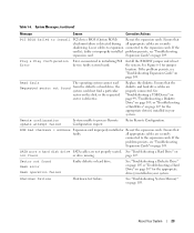
...) Option Description CPU Information Displays information related to each of the integrated devices on ). Available options can include the diskette drive, CD drive, hard drives, and network. PCI IRQ Assignment Displays a screen to change the IRQ assigned to microprocessors (speed, cache size, and ... changing the setting of keyboard errors during POST. Boot Sequence Determines the order in the system. Hard-Disk Drive Sequence Specifies the order in which hard drives are configured in which the system searches for boot devices during system startup. Integrated Devices See "...
...) Option Description CPU Information Displays information related to each of the integrated devices on ). Available options can include the diskette drive, CD drive, hard drives, and network. PCI IRQ Assignment Displays a screen to change the IRQ assigned to microprocessors (speed, cache size, and ... changing the setting of keyboard errors during POST. Boot Sequence Determines the order in the system. Hard-Disk Drive Sequence Specifies the order in which hard drives are configured in which the system searches for boot devices during system startup. Integrated Devices See "...

Hardware Owner's Manual
Page 32
...lists the options and descriptions for the integrated 10/100/1000 NIC. Diskette Controller (Auto default) Enables or disables the system's diskette drive controller. User Accessible USB Ports Enables or disables the system's user accessible USB ports. If both input and output data. 32 Using ... shares the same IRQ setting. Parallel Port (378h default) Selects the address for the parallel port. Optional Hard-Disk Drive Displays Installed if the optional fourth hard-drive carrier fan cable is connected to Fan the system board connector and is set the serial port to Auto ...
...lists the options and descriptions for the integrated 10/100/1000 NIC. Diskette Controller (Auto default) Enables or disables the system's diskette drive controller. User Accessible USB Ports Enables or disables the system's user accessible USB ports. If both input and output data. 32 Using ... shares the same IRQ setting. Parallel Port (378h default) Selects the address for the parallel port. Optional Hard-Disk Drive Displays Installed if the optional fourth hard-drive carrier fan cable is connected to Fan the system board connector and is set the serial port to Auto ...

Hardware Owner's Manual
Page 41
Installing System Components This section describes how to install the following system components: • Front drive bezel • Hard drives • Diskette drive • Optical and tape drives • Expansion cards • SAS controller card • Microprocessor • Memory • System battery • Power supply • Cooling Fans • Chassis intrusion switch • ...
Installing System Components This section describes how to install the following system components: • Front drive bezel • Hard drives • Diskette drive • Optical and tape drives • Expansion cards • SAS controller card • Microprocessor • Memory • System battery • Power supply • Cooling Fans • Chassis intrusion switch • ...

Hardware Owner's Manual
Page 42
... peripherals through a single nonredundant power supply. 42 Installing System Components The rotatable hard-drive carrier provides space for an optical drive; Inside the System 3 2 1 4 5 10 9 8 6 7 1 5.25-inch drive bays (2) 4 system board 7 rotatable hard-drive carrier 10 flex bay 2 drive cage 5 memory fan 8 front fan 3 power supply 6 hard drives (2) 9 expansion-card fan The system board can accommodate two processors, five...
... peripherals through a single nonredundant power supply. 42 Installing System Components The rotatable hard-drive carrier provides space for an optical drive; Inside the System 3 2 1 4 5 10 9 8 6 7 1 5.25-inch drive bays (2) 4 system board 7 rotatable hard-drive carrier 10 flex bay 2 drive cage 5 memory fan 8 front fan 3 power supply 6 hard drives (2) 9 expansion-card fan The system board can accommodate two processors, five...

Hardware Owner's Manual
Page 44
... any procedure, see your Product Information Guide for complete information about safety precautions, working inside the system. Opening and Closing the System 1 1 release tab Rotatable Hard-Drive Carrier Rotating the Hard-Drive Carrier Out of the components inside the computer and protecting against the rotatable...
... any procedure, see your Product Information Guide for complete information about safety precautions, working inside the system. Opening and Closing the System 1 1 release tab Rotatable Hard-Drive Carrier Rotating the Hard-Drive Carrier Out of the components inside the computer and protecting against the rotatable...


