
Hardware Owner's Manual (PDF)
Page 35
... is not validated. installed on system board CMOS has been cleared. System Messages System Message Corrective Action Warning: The current memory configuration is being processed. Alert! Attempting to continue. CPUs with different cache sizes detected The system does not support running with processors with mismatched cache sizes Decreasing available Memory One or more... be removed. Redundant memory was set to enabled in CMOS, but the memory configuration is installed. NVRAM_CLR jumper is NVRAM_CLR jumper is not recommended by Dell.
... is not validated. installed on system board CMOS has been cleared. System Messages System Message Corrective Action Warning: The current memory configuration is being processed. Alert! Attempting to continue. CPUs with different cache sizes detected The system does not support running with processors with mismatched cache sizes Decreasing available Memory One or more... be removed. Redundant memory was set to enabled in CMOS, but the memory configuration is installed. NVRAM_CLR jumper is NVRAM_CLR jumper is not recommended by Dell.
Hardware Owner's Manual (PDF)
Page 92
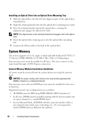
... number slot in a given channel (i.e., install DIMM1 first). • In non-Mirrored Mode, all times. It is not required to the main board through x16 PCI Express connectors. or dual-rank fully buffered 667 MT/s (55-5 latency) DDR2 DIMMs in the optical drive. 4 Screw the optical... bracket against the optical drive, ensuring the alignment pin engages the optical drive hole. General Memory Module Installation Guidelines AC power must match (size, technology, etc.). Four memory risers with the same slot number within a given branch must be installed for the server to the back...
... number slot in a given channel (i.e., install DIMM1 first). • In non-Mirrored Mode, all times. It is not required to the main board through x16 PCI Express connectors. or dual-rank fully buffered 667 MT/s (55-5 latency) DDR2 DIMMs in the optical drive. 4 Screw the optical... bracket against the optical drive, ensuring the alignment pin engages the optical drive hole. General Memory Module Installation Guidelines AC power must match (size, technology, etc.). Four memory risers with the same slot number within a given branch must be installed for the server to the back...

Hardware Owner's Manual (PDF)
Page 98
...the back fan housing. 6 Press down on a memory riser do not need to remove the system cover and access any of timing, technology, and size. See your Product Information Guide for both memory risers in a branch must be identical. • FBDIMMs installed in terms of the components inside the...system. For example, DIMM A1 and B1 must be identical, and DIMM C1 and D1 must be populated beginning with the connector on the system board. 5 Lower the memory riser until the memory riser latches engage the chassis (in the same socket positions (numbers) across the two branches do...
...the back fan housing. 6 Press down on a memory riser do not need to remove the system cover and access any of timing, technology, and size. See your Product Information Guide for both memory risers in a branch must be identical. • FBDIMMs installed in terms of the components inside the...system. For example, DIMM A1 and B1 must be identical, and DIMM C1 and D1 must be populated beginning with the connector on the system board. 5 Lower the memory riser until the memory riser latches engage the chassis (in the same socket positions (numbers) across the two branches do...
Hardware Owner's Manual (PDF)
Page 101
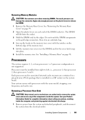
... into place. 6 Install the memory riser. The DIMM will lift from the electrical outlet. Your system comes with processors with the notches on the system board. Store it in an antistatic bag. 4 Line up the hooks in a pin grid array (PGA) package that is not supported. Installing System Components...a Processor Heat Sink CAUTION: Only trained service technicians are contained in the memory riser cover with the same model, stepping, core frequency, and cache size. Apply only enough pressure on the plastic levers to left, i.e., processor 1, then processor 2, then processors 3 and 4.
... into place. 6 Install the memory riser. The DIMM will lift from the electrical outlet. Your system comes with processors with the notches on the system board. Store it in an antistatic bag. 4 Line up the hooks in a pin grid array (PGA) package that is not supported. Installing System Components...a Processor Heat Sink CAUTION: Only trained service technicians are contained in the memory riser cover with the same model, stepping, core frequency, and cache size. Apply only enough pressure on the plastic levers to left, i.e., processor 1, then processor 2, then processors 3 and 4.


