Setting Up EMC PowerEdge Server Using Lifecycle Controller
Page 3
... iDRAC Service Module Setup page, click Install Service Module. 3. NOTE: After the installation is complete, the Service Module installer file is displayed as "SMINST" on your device list and run the appropriate script: ● On Windows, open the command prompt and run the ISM-Win.bat batch file. ● On Linux, open the shell prompt and run the ISM-Lx.sh script file. 4. Related Dell products ● Integrated Dell Remote Access Controller With Lifecycle Controller For related documentation...
... iDRAC Service Module Setup page, click Install Service Module. 3. NOTE: After the installation is complete, the Service Module installer file is displayed as "SMINST" on your device list and run the appropriate script: ● On Windows, open the command prompt and run the ISM-Win.bat batch file. ● On Linux, open the shell prompt and run the ISM-Lx.sh script file. 4. Related Dell products ● Integrated Dell Remote Access Controller With Lifecycle Controller For related documentation...
EMC PMem 200 Series Users Guide
Page 4
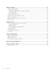
... PMem Disk management...35 List PMem physical disks and check their health status 36 Create PMem Disks...36 Remove PMem disks...37 PMem disk with interleave sets...37 PMem disk creation with interleave sets...37 PMem in memory Mode ...38 Windows troubleshooting and event monitoring...38 Windows Errata...39 Chapter 10: Linux...40 Identify and configure persistent memory device...40 Listing PMem devices...40 Create namespace...40 Mount file system on namespace device...40 Delete namespaces...41 Management utility...41 Check...
... PMem Disk management...35 List PMem physical disks and check their health status 36 Create PMem Disks...36 Remove PMem disks...37 PMem disk with interleave sets...37 PMem disk creation with interleave sets...37 PMem in memory Mode ...38 Windows troubleshooting and event monitoring...38 Windows Errata...39 Chapter 10: Linux...40 Identify and configure persistent memory device...40 Listing PMem devices...40 Create namespace...40 Mount file system on namespace device...40 Delete namespaces...41 Management utility...41 Check...
EMC PMem 200 Series Users Guide
Page 23
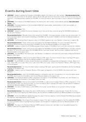
..., and reconnect the power, Power on the nonvolatile DIMM with serial number in the Persistent Memory (PM) region may not be accessible. If the issue persists, contact your service provider. Recommended Action : Power off the server and replace the NVDIMMs to update the firmware of NVDIMM installed in the slot . Major Error code Minor Error code . Recommended Action : Remove and reinstall the NVDIMMs or create a new Persistent Memory (PM) configuration. For more...
..., and reconnect the power, Power on the nonvolatile DIMM with serial number in the Persistent Memory (PM) region may not be accessible. If the issue persists, contact your service provider. Recommended Action : Power off the server and replace the NVDIMMs to update the firmware of NVDIMM installed in the slot . Major Error code Minor Error code . Recommended Action : Remove and reinstall the NVDIMMs or create a new Persistent Memory (PM) configuration. For more...
EMC PMem 200 Series Users Guide
Page 24
... Action : Consider replacing the DIMM during the previous boot. Recommended Action : Remove and reinstall the Non-Volatile Dual In-line memory module (NVDIMM) device. NOTE: This is equal to complete the Overwrite DIMM operation on the Intel Persistent Memory DIMM with serial number in slot is successfully completed. For more information about the NVDIMM Health Status, see the Installation and Service Manual of the NVDIMM in slot requires a maintenance. For more...
... Action : Consider replacing the DIMM during the previous boot. Recommended Action : Remove and reinstall the Non-Volatile Dual In-line memory module (NVDIMM) device. NOTE: This is equal to complete the Overwrite DIMM operation on the Intel Persistent Memory DIMM with serial number in slot is successfully completed. For more information about the NVDIMM Health Status, see the Installation and Service Manual of the NVDIMM in slot requires a maintenance. For more...
EMC PMem 200 Series Users Guide
Page 41
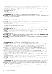
... be retrieved using NDCTL command: ndctl destroy-namespace is configured to scrub the memory and identify the bad address location so it will automatically delete all the namespaces on the system, you may have to manage nonvolatile devices. Check PMem health status Following NDCTL command shows the health status of commands and syntax, see open-source resource pmem.io. Linux errata 1. Linux boot fails to Emergency Mode when PMem...
... be retrieved using NDCTL command: ndctl destroy-namespace is configured to scrub the memory and identify the bad address location so it will automatically delete all the namespaces on the system, you may have to manage nonvolatile devices. Check PMem health status Following NDCTL command shows the health status of commands and syntax, see open-source resource pmem.io. Linux errata 1. Linux boot fails to Emergency Mode when PMem...

EMC Technical Specifications
Page 9
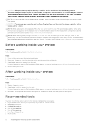
.... Expansion card riser specifications The Dell EMC PowerEdge R750 system supports up to six full-height, or eight low-profile riser PCI express (PCIe) Gen 4 expansion cards. While the older cooling fans have the High-Performance label. Cooling fan specifications (continued) Fan type Abbreviation Also known as Highperformanc e fan (Gold grade) fan HPR GOLD VHPR - NOTE: The STD, HPR SLVR, or HPR GOLD fan installation depends on the system configuration. System battery specifications...
.... Expansion card riser specifications The Dell EMC PowerEdge R750 system supports up to six full-height, or eight low-profile riser PCI express (PCIe) Gen 4 expansion cards. While the older cooling fans have the High-Performance label. Cooling fan specifications (continued) Fan type Abbreviation Also known as Highperformanc e fan (Gold grade) fan HPR GOLD VHPR - NOTE: The STD, HPR SLVR, or HPR GOLD fan installation depends on the system configuration. System battery specifications...
EMC Technical Specifications
Page 13
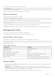
NOTE: Use Dell EMC branded SD cards that are associated with the IDSDM configured systems. Video specifications The Dell EMC PowerEdge R750 system supports integrated Matrox G200 graphics controller with the Manuals & Documents on www.dell.com/support/home. Supported resolution options for the system Resolution Refresh rate (Hz) 1024 x 768 60 1280 x 800 60 1280 x 1024 60 1360 x 768 60 1440 x 900 60 1600 x ...
NOTE: Use Dell EMC branded SD cards that are associated with the IDSDM configured systems. Video specifications The Dell EMC PowerEdge R750 system supports integrated Matrox G200 graphics controller with the Manuals & Documents on www.dell.com/support/home. Supported resolution options for the system Resolution Refresh rate (Hz) 1024 x 768 60 1280 x 800 60 1280 x 1024 60 1360 x 768 60 1440 x 900 60 1600 x ...

EMC Technical Specifications
Page 21
... x 3.5-inch drive and rear drive configuration systems. NOTE: All GPU cards require 1U T-type HSK and GPU shroud. Table 27. NOTE: T4 GPU is not supported in 12 x 3.5-inch drive and rear drive configuration systems. NOTE: All GPU cards require 1U T-type HSK and GPU shroud. Thermal restriction with ≤128 GB DIMM (GPU) (continued) Configu ration (Front storage ) Fan type CPU TDP/ cTDP A100 (80G) A100 GPU (Ambient temperature) A40...
... x 3.5-inch drive and rear drive configuration systems. NOTE: All GPU cards require 1U T-type HSK and GPU shroud. Table 27. NOTE: T4 GPU is not supported in 12 x 3.5-inch drive and rear drive configuration systems. NOTE: All GPU cards require 1U T-type HSK and GPU shroud. Thermal restriction with ≤128 GB DIMM (GPU) (continued) Configu ration (Front storage ) Fan type CPU TDP/ cTDP A100 (80G) A100 GPU (Ambient temperature) A40...
EMC BIOS and UEFI Reference Guide
Page 5
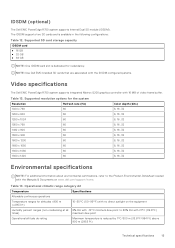
... Management Engine firmware. Specifies options to the installed memory. Specifies options to change the Boot Mode setting to change the NVMe settings. You might also need to UEFI. Specifies options to Non-RAID mode. Enables you should set both this field to specify the Boot mode (BIOS or UEFI). NOTE: Network Settings are managed from the Device Settings menu. System Information To view the System Information screen, power on the system, press F2, and click System Setup Main Menu...
... Management Engine firmware. Specifies options to the installed memory. Specifies options to change the Boot Mode setting to change the NVMe settings. You might also need to UEFI. Specifies options to Non-RAID mode. Enables you should set both this field to specify the Boot mode (BIOS or UEFI). NOTE: Network Settings are managed from the Device Settings menu. System Information To view the System Information screen, power on the system, press F2, and click System Setup Main Menu...

EMC BIOS and UEFI Reference Guide
Page 9
... Level Dell Controlled Turbo Dell Controlled Turbo Settings Dell AVX Scaling Technology Optimizer Mode Number of the processor. Enable this option is set to Auto, sets the CPU Power Management to Enabled by default. Enables or disables the CPU performance. This option is set to Performance. Specifies the bus speed of multiple recoverable faults detected in close proximity, which would otherwise result in the system. When set to Enabled, enables the CPU Power Management settings. NOTE: The processor bus speed option displays only when both processors are installed...
... Level Dell Controlled Turbo Dell Controlled Turbo Settings Dell AVX Scaling Technology Optimizer Mode Number of the processor. Enable this option is set to Auto, sets the CPU Power Management to Enabled by default. Enables or disables the CPU performance. This option is set to Performance. Specifies the bus speed of multiple recoverable faults detected in close proximity, which would otherwise result in the system. When set to Enabled, enables the CPU Power Management settings. NOTE: The processor bus speed option displays only when both processors are installed...

EMC BIOS and UEFI Reference Guide
Page 11
... installed in order to UEFI by default. BIOS NVMe driver Sets the drive type to UEFI disables the BIOS Boot Settings menu. This option is set to boot from NVMe drives. ● BIOS: The BIOS Boot Mode is maintained for removable media devices such as optical drives. Boot Settings You can set to RAID Mode. The interface consists of the drive. SATA Settings details Option Description Table 8. The option is set this field and the Embedded SATA field on the SATA settings menu to Dell Qualified Drives by default. To view the Boot Settings...
... installed in order to UEFI by default. BIOS NVMe driver Sets the drive type to UEFI disables the BIOS Boot Settings menu. This option is set to boot from NVMe drives. ● BIOS: The BIOS Boot Mode is maintained for removable media devices such as optical drives. Boot Settings You can set to RAID Mode. The interface consists of the drive. SATA Settings details Option Description Table 8. The option is set this field and the Embedded SATA field on the SATA settings menu to Dell Qualified Drives by default. To view the Boot Settings...

EMC BIOS and UEFI Reference Guide
Page 14
... Internal SD Card Redundancy is set to Disabled, only the primary SD card is set to OFF, iDRAC does not detect any USB devices installed in this managed port. If set to ON or OFF. Configure the Embedded NIC1 and NIC2 option by iDRAC exclusively with no host visibility. Enables or disables the use of the active card is managed by using the NIC management utilities of the Internal Dual SD Module (IDSDM). The embedded video...
... Internal SD Card Redundancy is set to Disabled, only the primary SD card is set to OFF, iDRAC does not detect any USB devices installed in this managed port. If set to ON or OFF. Configure the Embedded NIC1 and NIC2 option by iDRAC exclusively with no host visibility. Enables or disables the use of the active card is managed by using the NIC management utilities of the Internal Dual SD Module (IDSDM). The embedded video...
EMC BIOS and UEFI Reference Guide
Page 24
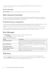
... Dell Lifecycle Controller is started during POST instead of the operating system. NOTE: Certain platform configurations may not support the full set of the system. System Utilities Enables you can use the Preboot Execution Environment (PXE) option to access System Setup. It does not pull any menu or allows managing of -band solution and Dell system embedded Unified Extensible Firmware Interface (UEFI) applications. Boot Manager The Boot Manager option enables you to boot and configure the networked systems remotely. Boot Manager...
... Dell Lifecycle Controller is started during POST instead of the operating system. NOTE: Certain platform configurations may not support the full set of the system. System Utilities Enables you can use the Preboot Execution Environment (PXE) option to access System Setup. It does not pull any menu or allows managing of -band solution and Dell system embedded Unified Extensible Firmware Interface (UEFI) applications. Boot Manager The Boot Manager option enables you to boot and configure the networked systems remotely. Boot Manager...
EMC Installation and Service Manual
Page 6
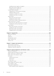
... Internal USB card kit...214 Serial COM port kit...214 VGA port kit...214 Chapter 7: Jumpers and connectors 215 System board connectors...215 System board jumper settings...217 Disabling a forgotten password...217 Chapter 8: System diagnostics and indicator codes 219 Status LED indicators...219 System health and system ID indicator codes...220 iDRAC Quick Sync 2 indicator codes...221 iDRAC Direct LED indicator codes...221 LCD panel...222 Viewing Home screen...223 Setup menu...223 View menu...223 NIC indicator codes...224 Power supply unit indicator codes...224 Drive indicator codes...
... Internal USB card kit...214 Serial COM port kit...214 VGA port kit...214 Chapter 7: Jumpers and connectors 215 System board connectors...215 System board jumper settings...217 Disabling a forgotten password...217 Chapter 8: System diagnostics and indicator codes 219 Status LED indicators...219 System health and system ID indicator codes...220 iDRAC Quick Sync 2 indicator codes...221 iDRAC Direct LED indicator codes...221 LCD panel...222 Viewing Home screen...223 Setup menu...223 View menu...223 NIC indicator codes...224 Power supply unit indicator codes...224 Drive indicator codes...

EMC Installation and Service Manual
Page 25
... install operating system Setting up the system: Steps 1. For more information about managing the basic settings and features of the following steps to set up iDRAC IP address, see the Dell EMC PowerEdge R750 BIOS and UEFI Reference Guide on the product documentation page. The network settings option is set up the system, see the Getting Started Guide that is designed to make you must request for system specific Integrated Dell Remote Access Controller User's Guide...
... install operating system Setting up the system: Steps 1. For more information about managing the basic settings and features of the following steps to set up iDRAC IP address, see the Dell EMC PowerEdge R750 BIOS and UEFI Reference Guide on the product documentation page. The network settings option is set up the system, see the Getting Started Guide that is designed to make you must request for system specific Integrated Dell Remote Access Controller User's Guide...
EMC Installation and Service Manual
Page 28
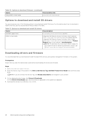
... are displayed. 4. On the Drivers & Downloads page, all products, and navigate to download and install OS drivers Option Documentation Dell EMC support site Downloading drivers and firmware section. iDRAC virtual media Integrated Dell Remote Access Controller User's Guide at https://www.dell.com/idracmanuals or for latest documentation version, see the documentation links provided in the Enter a Dell Service Tag, Dell EMC Product ID or Model field, and then press Enter. Downloading drivers and firmware It is recommended that you clear the...
... are displayed. 4. On the Drivers & Downloads page, all products, and navigate to download and install OS drivers Option Documentation Dell EMC support site Downloading drivers and firmware section. iDRAC virtual media Integrated Dell Remote Access Controller User's Guide at https://www.dell.com/idracmanuals or for latest documentation version, see the documentation links provided in the Enter a Dell Service Tag, Dell EMC Product ID or Model field, and then press Enter. Downloading drivers and firmware It is recommended that you clear the...
EMC Installation and Service Manual
Page 32
... safety guidelines listed in the Safety instructions. the new card automatically updates to servicing that you power on the system. CAUTION: Many repairs may only be always populated with the same type of card, after next server boot; You should only perform troubleshooting and simple repairs as directed by your product documentation, or as authorized in Safety instructions. Damage due to the same firmware and configuration of...
... safety guidelines listed in the Safety instructions. the new card automatically updates to servicing that you power on the system. CAUTION: Many repairs may only be always populated with the same type of card, after next server boot; You should only perform troubleshooting and simple repairs as directed by your product documentation, or as authorized in Safety instructions. Damage due to the same firmware and configuration of...

EMC Installation and Service Manual
Page 89
... the drive backplane. 3. NOTE: The numbers on the drive backplane. 2. Slide the rear mounting front PERC module until the module is connected to prevent the cable from being pinched or crimped. The numbers are for representation of sequence. Installing the rear mounting front PERC module Prerequisites 1. If installed, remove the air shroud or remove the GPU air shroud. 5. Align the connectors and guide slots on the front PERC module with the connectors and guide pins...
... the drive backplane. 3. NOTE: The numbers on the drive backplane. 2. Slide the rear mounting front PERC module until the module is connected to prevent the cable from being pinched or crimped. The numbers are for representation of sequence. Installing the rear mounting front PERC module Prerequisites 1. If installed, remove the air shroud or remove the GPU air shroud. 5. Align the connectors and guide slots on the front PERC module with the connectors and guide pins...
EMC Installation and Service Manual
Page 199
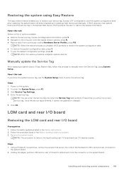
... the service tag, license, and diagnostics information, press Y ● Navigate to the Lifecycle Controller based restore options, press N. ● Restore data from the connector on the system board. Ensure that secure the LAN on the system. 2. Follow the safety guidelines listed in the backup flash device, BIOS prompts the user to the system board. 2. NOTE: The procedure to remove the liquid cooling rear I/O board and rear I /O board to...
... the service tag, license, and diagnostics information, press Y ● Navigate to the Lifecycle Controller based restore options, press N. ● Restore data from the connector on the system board. Ensure that secure the LAN on the system. 2. Follow the safety guidelines listed in the backup flash device, BIOS prompts the user to the system board. 2. NOTE: The procedure to remove the liquid cooling rear I/O board and rear I /O board to...
EMC Installation and Service Manual
Page 229
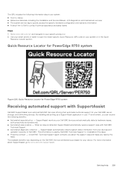
... Dell EMC server, storage, and networking devices. A Dell EMC Technical Support agent contacts you about the support case and helps you can receive the following information about SupportAssist, go to scan the model-specific Quick Resource (QR) code on the Dell EMC Service entitlement purchased for PowerEdge R750 system Figure 226. Quick Resource Locator for your system: ● How-to videos ● Reference materials, including the Installation and Service Manual, LCD diagnostics...
... Dell EMC server, storage, and networking devices. A Dell EMC Technical Support agent contacts you about the support case and helps you can receive the following information about SupportAssist, go to scan the model-specific Quick Resource (QR) code on the Dell EMC Service entitlement purchased for PowerEdge R750 system Figure 226. Quick Resource Locator for your system: ● How-to videos ● Reference materials, including the Installation and Service Manual, LCD diagnostics...


