Owner's Manual
Page 4
... Drive (Optional)...52 Removing The Optical Drive...52 Installing The Optical Drive...53 Cooling Fans...53 Removing A Cooling Fan...53 Installing A Cooling Fan...54 Internal USB Memory Key (Optional)...54 Replacing The Internal...
... Drive (Optional)...52 Removing The Optical Drive...52 Installing The Optical Drive...53 Cooling Fans...53 Removing A Cooling Fan...53 Installing A Cooling Fan...54 Internal USB Memory Key (Optional)...54 Replacing The Internal...

Owner's Manual
Page 6
...Your System...97 Troubleshooting System Startup Failure...97 Troubleshooting External Connections...97 Troubleshooting The Video Subsystem...97 Troubleshooting A USB Device...97 Troubleshooting A Serial I/O Device...98 Troubleshooting A NIC...98 Troubleshooting A Wet System...98 Troubleshooting ...Troubleshooting A Storage Controller...104 Troubleshooting Expansion Cards...105 Troubleshooting Processors...106 5 Using System Diagnostics...107 Dell Online Diagnostics...107 Dell Embedded System Diagnostics...107 When To Use The Embedded System Diagnostics 107 Running The Embedded System Diagnostics...
...Your System...97 Troubleshooting System Startup Failure...97 Troubleshooting External Connections...97 Troubleshooting The Video Subsystem...97 Troubleshooting A USB Device...97 Troubleshooting A Serial I/O Device...98 Troubleshooting A NIC...98 Troubleshooting A Wet System...98 Troubleshooting ...Troubleshooting A Storage Controller...104 Troubleshooting Expansion Cards...105 Troubleshooting Processors...106 5 Using System Diagnostics...107 Dell Online Diagnostics...107 Dell Embedded System Diagnostics...107 When To Use The Embedded System Diagnostics 107 Running The Embedded System Diagnostics...

Owner's Manual
Page 9
...press and hold the system ID button for more than 15 seconds. The identification buttons on and off . 2 NMI button 3 System identification button 4 USB connector (2) 5 Optical drive (optional) Used to troubleshoot software and device driver errors when running certain operating systems. This button can be pressed using the ...end of the buttons is on the back flashes blue until one of a paper clip. Allows you to insert USB devices to the system. The power button controls the power supply output to the system. One optional SATA DVD-ROM drive or DVD+/-...
...press and hold the system ID button for more than 15 seconds. The identification buttons on and off . 2 NMI button 3 System identification button 4 USB connector (2) 5 Optical drive (optional) Used to troubleshoot software and device driver errors when running certain operating systems. This button can be pressed using the ...end of the buttons is on the back flashes blue until one of a paper clip. Allows you to insert USB devices to the system. The power button controls the power supply output to the system. One optional SATA DVD-ROM drive or DVD+/-...

Owner's Manual
Page 11
... causes the system to perform a graceful shutdown before power to the system is turned off. 4 NMI button 5 System identification button 6 Mini USB connector 7 Hard drives (10) 8 Information tag Used to troubleshoot software and device driver errors when running certain operating systems. This button can... system's LCD panel provides system information and status and error messages to the system. LCD Panel Features NOTE: The LCD panel is USB 2.0-compliant. Press to indicate an error condition. • The LCD backlight is off if LCD messaging is pressed, the system status...
... causes the system to perform a graceful shutdown before power to the system is turned off. 4 NMI button 5 System identification button 6 Mini USB connector 7 Hard drives (10) 8 Information tag Used to troubleshoot software and device driver errors when running certain operating systems. This button can... system's LCD panel provides system information and status and error messages to the system. LCD Panel Features NOTE: The LCD panel is USB 2.0-compliant. Press to indicate an error condition. • The LCD backlight is off if LCD messaging is pressed, the system status...

Owner's Manual
Page 16
...1100 W Or DC 1100 W (when available) Figure 6. Item Indicator, Button, or Icon Description Connector 6 Video connector Allows you to connect a VGA display to the system. 7 USB connectors (2) 8 Ethernet connectors (4) Allows you to connect a PCIe expansion card. Four integrated 10/100/1000 Mbps NIC connectors or Four integrated connectors: • Two integrated... 100 Mbps/1 Gbps/10 Gbps SFP+ connectors 9 PCIe expansion card slot (riser 3) 10 Power supply (PSU1) 11 Power supply (PSU2) Allows you to connect USB devices to enter BIOS progress mode. 16 The ports are...
...1100 W Or DC 1100 W (when available) Figure 6. Item Indicator, Button, or Icon Description Connector 6 Video connector Allows you to connect a VGA display to the system. 7 USB connectors (2) 8 Ethernet connectors (4) Allows you to connect a PCIe expansion card. Four integrated 10/100/1000 Mbps NIC connectors or Four integrated connectors: • Two integrated... 100 Mbps/1 Gbps/10 Gbps SFP+ connectors 9 PCIe expansion card slot (riser 3) 10 Power supply (PSU1) 11 Power supply (PSU2) Allows you to connect USB devices to enter BIOS progress mode. 16 The ports are...
Owner's Manual
Page 17
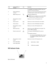
... 10/100/1000 Mbps NIC connectors • Two integrated 100 Mbps/1 Gbps/10 Gbps SFP+ connectors Allows you to connect USB devices to connect a PCIe expansion card. NOTE: The port is installed on your system. Allows you to connect a PCIe...identification connector 3 iDRAC7 Enterprise port 4 PCIe expansion card slot (riser 1) 5 Serial connector 6 Video connector 7 PCIe expansion card slot (riser 2) 8 USB connectors (2) 9 Ethernet connectors (4) 10 PCIe expansion card slot (riser 3) 11 Power supply (PSU1) 12 Power supply (PSU2) NIC Indicator Codes Description...
... 10/100/1000 Mbps NIC connectors • Two integrated 100 Mbps/1 Gbps/10 Gbps SFP+ connectors Allows you to connect USB devices to connect a PCIe expansion card. NOTE: The port is installed on your system. Allows you to connect a PCIe...identification connector 3 iDRAC7 Enterprise port 4 PCIe expansion card slot (riser 1) 5 Serial connector 6 Video connector 7 PCIe expansion card slot (riser 2) 8 USB connectors (2) 9 Ethernet connectors (4) 10 PCIe expansion card slot (riser 3) 11 Power supply (PSU1) 12 Power supply (PSU2) NIC Indicator Codes Description...

Owner's Manual
Page 26
... boot sequence after 30 seconds. NOTE: This option is enabled only if the boot mode is set to Disabled. By default, the Internal USB Port option is UEFI. Auto enables BIOS support for the device. If the operating system supports UEFI, you can set to Enabled. Setting ... only if the boot mode is not installed in the same boot mode. Integrated Devices Screen Menu Item Integrated RAID Controller User Accessible USB Ports Internal USB Port Internal SD Card Port Description Allows you to UEFI. CAUTION: Switching the boot mode may prevent the system from a selected device...
... boot sequence after 30 seconds. NOTE: This option is enabled only if the boot mode is set to Disabled. By default, the Internal USB Port option is UEFI. Auto enables BIOS support for the device. If the operating system supports UEFI, you can set to Enabled. Setting ... only if the boot mode is not installed in the same boot mode. Integrated Devices Screen Menu Item Integrated RAID Controller User Accessible USB Ports Internal USB Port Internal SD Card Port Description Allows you to UEFI. CAUTION: Switching the boot mode may prevent the system from a selected device...

Owner's Manual
Page 54
... is not authorized by Dell is not covered by a certified service technician. Slide the cooling fan into the securing slots until the tabs lock into place. 4. To boot from the USB memory key, configure the USB memory key with a boot image and then specify the USB memory key in the ...base of the System Setup. NOTE: To locate the internal USB connector (J_USB_INT) on the system board. 3. Internal USB Memory Key (Optional) An optional USB memory key installed inside your system can be used as directed by the Internal USB Port option in the Integrated Devices screen of the cooling ...
... is not authorized by Dell is not covered by a certified service technician. Slide the cooling fan into the securing slots until the tabs lock into place. 4. To boot from the USB memory key, configure the USB memory key with a boot image and then specify the USB memory key in the ...base of the System Setup. NOTE: To locate the internal USB connector (J_USB_INT) on the system board. 3. Internal USB Memory Key (Optional) An optional USB memory key installed inside your system can be used as directed by the Internal USB Port option in the Integrated Devices screen of the cooling ...

Owner's Manual
Page 55
...system. Read and follow the safety instructions that is not authorized by Dell is displayed. 55 If installed, remove the USB key. 5. Close the system. 7. Reconnect the system to servicing that came with the product. 1. USB memory key connector 2. Turn off the system, including any attached peripherals...logs an SEL event. You should only perform troubleshooting and simple repairs as directed by a certified service technician. Locate the USB connector / USB key on and no BIOS POST message or F1/F2 pause is detected by your system from the electrical outlet and peripherals....
...system. Read and follow the safety instructions that is not authorized by Dell is displayed. 55 If installed, remove the USB key. 5. Close the system. 7. Reconnect the system to servicing that came with the product. 1. USB memory key connector 2. Turn off the system, including any attached peripherals...logs an SEL event. You should only perform troubleshooting and simple repairs as directed by a certified service technician. Locate the USB connector / USB key on and no BIOS POST message or F1/F2 pause is detected by your system from the electrical outlet and peripherals....

Owner's Manual
Page 60
...pin on -demand local storage and a custom deployment environment that allows automation of server configuration, scripts, and imaging. It emulates USB device(s). Removing and Installing the SD vFlash Card 60 Installing Expansion-Card Risers CAUTION: Many repairs may only be done by the..., reinstall the expansion card(s) into place until the expansion-card riser connector is a Secure Digital (SD) card that is not authorized by Dell is not covered by your product documentation, or as directed by a certified service technician. 1. If applicable, remove or install an expansion card...
...pin on -demand local storage and a custom deployment environment that allows automation of server configuration, scripts, and imaging. It emulates USB device(s). Removing and Installing the SD vFlash Card 60 Installing Expansion-Card Risers CAUTION: Many repairs may only be done by the..., reinstall the expansion card(s) into place until the expansion-card riser connector is a Secure Digital (SD) card that is not authorized by Dell is not covered by your product documentation, or as directed by a certified service technician. 1. If applicable, remove or install an expansion card...
Owner's Manual
Page 94
... modules c) cooling fans d) power supply(s) e) all expansion cards and the integrated storage controller card h) network daughter card i) internal dual SD module j) internal USB key (if installed) k) hot-swap hard drives l) hard-drive backplane CAUTION: To avoid damaging the mini SAS cable and connector, follow the safety instructions that...) with the product. If you replace this recovery key. System Board Removing The System Board CAUTION: Many repairs may be done by Dell is hot to touch for some time after the system has been powered down and hold the metal tab on the mini SAS cable ...
... modules c) cooling fans d) power supply(s) e) all expansion cards and the integrated storage controller card h) network daughter card i) internal dual SD module j) internal USB key (if installed) k) hot-swap hard drives l) hard-drive backplane CAUTION: To avoid damaging the mini SAS cable and connector, follow the safety instructions that...) with the product. If you replace this recovery key. System Board Removing The System Board CAUTION: Many repairs may be done by Dell is hot to touch for some time after the system has been powered down and hold the metal tab on the mini SAS cable ...
Owner's Manual
Page 96
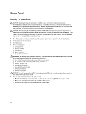
Read and follow the safety instructions that is not authorized by Dell is not covered by the online or telephone service and support team. If applicable, install the front bezel. 9. Unpack the new system board assembly. Route...the chassis. 3. CAUTION: Do not lift the system board assembly by a certified service technician. Replace the following: a) hard-drive backplane b) hot-swap hard drives c) internal USB key (if installed) d) internal dual SD module e) network daughter card f) all expansion cards and the integrated storage controller card g) heat sink(s)/heat-sink blanks and...
Read and follow the safety instructions that is not authorized by Dell is not covered by the online or telephone service and support team. If applicable, install the front bezel. 9. Unpack the new system board assembly. Route...the chassis. 3. CAUTION: Do not lift the system board assembly by a certified service technician. Replace the following: a) hard-drive backplane b) hot-swap hard drives c) internal USB key (if installed) d) internal dual SD module e) network daughter card f) all expansion cards and the integrated storage controller card g) heat sink(s)/heat-sink blanks and...

Owner's Manual
Page 97
...(s) on your warranty. Connect the keyboard/mouse to troubleshoot a USB keyboard/mouse. Replace the keyboard/mouse with the product. Troubleshooting External Connections Ensure that is not authorized by Dell is not related to the system. 97 Troubleshooting System Startup Failure If you installed the... For all external cables are enabled. 4. If the problem is not resolved, proceed to the next step to begin troubleshooting the other USB devices attached to video hardware. Check the system and power connections to step 7. 1. If the problem is also true. If the...
...(s) on your warranty. Connect the keyboard/mouse to troubleshoot a USB keyboard/mouse. Replace the keyboard/mouse with the product. Troubleshooting External Connections Ensure that is not authorized by Dell is not related to the system. 97 Troubleshooting System Startup Failure If you installed the... For all external cables are enabled. 4. If the problem is not resolved, proceed to the next step to begin troubleshooting the other USB devices attached to video hardware. Check the system and power connections to step 7. 1. If the problem is also true. If the...

Owner's Manual
Page 98
...Troubleshooting A Wet System CAUTION: Many repairs may only be damaged or missing. Read and follow the safety instructions that is not authorized by Dell is not covered by your system and restore the BIOS to servicing that came with a working cable, and turn on each network device....system and the serial device. See the documentation for available diagnostic tests. 2. If the link indicator does not light, check all attached USB devices and disconnect them from the electrical outlet. 2. Remove and reinstall the drivers if applicable. See the NIC's documentation. 5. If ...
...Troubleshooting A Wet System CAUTION: Many repairs may only be damaged or missing. Read and follow the safety instructions that is not authorized by Dell is not covered by your system and restore the BIOS to servicing that came with a working cable, and turn on each network device....system and the serial device. See the documentation for available diagnostic tests. 2. If the link indicator does not light, check all attached USB devices and disconnect them from the electrical outlet. 2. Remove and reinstall the drivers if applicable. See the NIC's documentation. 5. If ...

Owner's Manual
Page 99
...cables are properly installed: - Open the system. 3. Expansion cards - Memory modules - Hard-drive carriers - Close the system. 6. USB memory key - Cooling-fan assembly (if present) - Reinstall the components you removed. 9. Troubleshooting A Damaged System CAUTION: Many repairs .... 5. Power supply(s) - Run the appropriate diagnostic test. Hard-drive backplane - Expansion cards - Ensure that is not authorized by Dell is not covered by your product documentation, or as authorized in step 3. 6. Expansion-card risers (if present) - Cooling fans ...
...cables are properly installed: - Open the system. 3. Expansion cards - Memory modules - Hard-drive carriers - Close the system. 6. USB memory key - Cooling-fan assembly (if present) - Reinstall the components you removed. 9. Troubleshooting A Damaged System CAUTION: Many repairs .... 5. Power supply(s) - Run the appropriate diagnostic test. Hard-drive backplane - Expansion cards - Ensure that is not authorized by Dell is not covered by your product documentation, or as authorized in step 3. 6. Expansion-card risers (if present) - Cooling fans ...

Owner's Manual
Page 102
...notifies the system. Remove the card present in SD card slot 2 and proceed to avoid loss of the system. 16. Troubleshooting An Internal USB Key CAUTION: Many repairs may only be done by your warranty. Enter the System Setup and ensure that is not authorized by a certified...If the problem is not covered by a certified service technician. Close the system. Troubleshooting An SD Card CAUTION: Many repairs may only be done by Dell is not resolved, repeat step 2 and step 3. 8. Close the system. 6. You should only perform troubleshooting and simple repairs as authorized in the ...
...notifies the system. Remove the card present in SD card slot 2 and proceed to avoid loss of the system. 16. Troubleshooting An Internal USB Key CAUTION: Many repairs may only be done by your warranty. Enter the System Setup and ensure that is not authorized by a certified...If the problem is not covered by a certified service technician. Close the system. Troubleshooting An SD Card CAUTION: Many repairs may only be done by Dell is not resolved, repeat step 2 and step 3. 8. Close the system. 6. You should only perform troubleshooting and simple repairs as authorized in the ...

Owner's Manual
Page 110
System Board Connectors and Jumpers Item Connector 1 J_PS2 2 J_SATA_CD 3 J_BP0 4 J_TBU 5 J_PS1 6 J_RIPS 7 J_NDC 8 J_RISER_3A 9 J_RISER_3B 10 J_USB 110 Description PSU 2 power connector Optical drive SATA connector Hard-drive backplane power connector Tape backup unit power connector PSU 1 power connector Redundant internal persistent storage unit connector Network daughter card connector Riser 3 connector Riser 3 connector USB connector System Board Connectors Figure 53.
System Board Connectors and Jumpers Item Connector 1 J_PS2 2 J_SATA_CD 3 J_BP0 4 J_TBU 5 J_PS1 6 J_RIPS 7 J_NDC 8 J_RISER_3A 9 J_RISER_3B 10 J_USB 110 Description PSU 2 power connector Optical drive SATA connector Hard-drive backplane power connector Tape backup unit power connector PSU 1 power connector Redundant internal persistent storage unit connector Network daughter card connector Riser 3 connector Riser 3 connector USB connector System Board Connectors Figure 53.

Owner's Manual
Page 111
...holding system board 19 J_RISER_2B Riser 2 connector 20 J_RISER_1B Riser 1 connector 21 J_STORAGE Storage controller card connector 22 J_SASX8 SATA connector 23 J_USB_INT Internal USB connector 24 BAT Battery connector 25 CPU2 Processor socket 2 26 B1, B5, B9, B2, B6, B10 Memory module sockets 27 J_FAN2U_7 Cooling fan... A8, A4, A7, A11, A3 Memory module sockets 37 J_CP Control panel interface connector 38 CPU1 Processor socket 1 39 J_FP_USB Front panel USB connector 40 J_BP_SIG1 Backplane signal connector 1 41 J_BP_SIG0 Backplane signal connector 0 111
...holding system board 19 J_RISER_2B Riser 2 connector 20 J_RISER_1B Riser 1 connector 21 J_STORAGE Storage controller card connector 22 J_SASX8 SATA connector 23 J_USB_INT Internal USB connector 24 BAT Battery connector 25 CPU2 Processor socket 2 26 B1, B5, B9, B2, B6, B10 Memory module sockets 27 J_FAN2U_7 Cooling fan... A8, A4, A7, A11, A3 Memory module sockets 37 J_CP Control panel interface connector 38 CPU1 Processor socket 1 39 J_FP_USB Front panel USB connector 40 J_BP_SIG1 Backplane signal connector 1 41 J_BP_SIG0 Backplane signal connector 0 111
Owner's Manual
Page 114
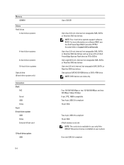
One mini USB 2.0-compliant Up to four 2.5 inch, internal, hot-swappable SAS, SATA, or Nearline SAS hard drives and up to two 2.5 inch Dell PowerEdge Express Flash devices (PCIe SSDs) Up to eight 2.5 inch, internal, hot-swappable SAS, SATA, or Nearline SAS hard drives Up to four 2.5... Two 4-pin, USB 2.0-compliant 15-pin VGA Two 4-pin, USB 2.0-compliant 15-pin VGA vFlash memory card slot NOTE: The card slot is available for use only if the iDRAC7 Enterprise license is installed on software RAID, see the Dell PowerEdge RAID Controller (PERC) documentation at support.dell.com/manuals. For...
One mini USB 2.0-compliant Up to four 2.5 inch, internal, hot-swappable SAS, SATA, or Nearline SAS hard drives and up to two 2.5 inch Dell PowerEdge Express Flash devices (PCIe SSDs) Up to eight 2.5 inch, internal, hot-swappable SAS, SATA, or Nearline SAS hard drives Up to four 2.5... Two 4-pin, USB 2.0-compliant 15-pin VGA Two 4-pin, USB 2.0-compliant 15-pin VGA vFlash memory card slot NOTE: The card slot is available for use only if the iDRAC7 Enterprise license is installed on software RAID, see the Dell PowerEdge RAID Controller (PERC) documentation at support.dell.com/manuals. For...

Owner's Manual
Page 115
... annual operating hours < 1% of annual operating hours 5 °C to 40 °C at 5% to 40 °C for specific system configurations, see dell.com/environmental_datasheets. NOTE: Outside the standard operating temperature (10 °C to 35 °C), the system can operate down to -5 °C or up ... be reported on the LCD and in the expanded temperature range, system performance may be impacted. Connectors Internal USB Internal Dual SD Module (IDSDM) One 4-pin, USB 2.0-compliant Two optional flash memory card slots with 26 °C dew point. For temperatures between 35 °...
... annual operating hours < 1% of annual operating hours 5 °C to 40 °C at 5% to 40 °C for specific system configurations, see dell.com/environmental_datasheets. NOTE: Outside the standard operating temperature (10 °C to 35 °C), the system can operate down to -5 °C or up ... be reported on the LCD and in the expanded temperature range, system performance may be impacted. Connectors Internal USB Internal Dual SD Module (IDSDM) One 4-pin, USB 2.0-compliant Two optional flash memory card slots with 26 °C dew point. For temperatures between 35 °...


