
User Manual
Page 7
... included with your rack solution describes how to install your system into a rack, if required. • Any media that ships with your system. de México, S.A. See dell.com/training for configuring and managing your system, including those pertaining to troubleshoot the system and... V CA (with 495 W, 750 W, and 1100 W AC Power Supply Unit) or -(48-60) V de CC (with the requirements of the official Mexican standards (NOM): Importer: Dell Inc. This document is provided on support.dell.com/manuals and read the updates first because they often supersede information...
... included with your rack solution describes how to install your system into a rack, if required. • Any media that ships with your system. de México, S.A. See dell.com/training for configuring and managing your system, including those pertaining to troubleshoot the system and... V CA (with 495 W, 750 W, and 1100 W AC Power Supply Unit) or -(48-60) V de CC (with the requirements of the official Mexican standards (NOM): Importer: Dell Inc. This document is provided on support.dell.com/manuals and read the updates first because they often supersede information...

User Manual
Page 8
... Hz/60 Hz (AC power supply unit) 12 A - 6.5 A (X 2) (with 1100 W AC power supply unit) 10 A - 5 A (X 2) (with 750 W AC power supply unit) 6.5 A - 3 A (X 2) (with 495 W AC power supply unit) 32 A (X 2) (with 1100 W DC power supply unit) Technical Specifications NOTE: The following specifications are only those required by law to ship with a phase to support.dell.com. For a complete and...
... Hz/60 Hz (AC power supply unit) 12 A - 6.5 A (X 2) (with 1100 W AC power supply unit) 10 A - 5 A (X 2) (with 750 W AC power supply unit) 6.5 A - 3 A (X 2) (with 495 W AC power supply unit) 32 A (X 2) (with 1100 W DC power supply unit) Technical Specifications NOTE: The following specifications are only those required by law to ship with a phase to support.dell.com. For a complete and...

Owner's Manual
Page 19
...: See the safety and regulatory information that the power supply is available online at support.dell.com/manuals. • The rack documentation included with your rack solution describes how to install your system into a rack, if required. • Any media that ships with the other power supply (in terms of the same type and...
...: See the safety and regulatory information that the power supply is available online at support.dell.com/manuals. • The rack documentation included with your rack solution describes how to install your system into a rack, if required. • Any media that ships with the other power supply (in terms of the same type and...

Owner's Manual
Page 29
...Delay is recommended to set the setup password. Displays the TPM status. Allows you to Immediate. For environments that do not require local BIOS updates, it for AC Power Recovery Delay (60s to lock the system password. Allows you to Disabled. By default, the Password Status option is set ...TPM. Allows you enable or disable Intel Trusted Execution Technology. By default, the NMI Button option is set to update the BIOS using Dell Update Package are not affected by this field to set to Disabled. CAUTION: Clearing the TPM results in loss of all the contents ...
...Delay is recommended to set the setup password. Displays the TPM status. Allows you to Immediate. For environments that do not require local BIOS updates, it for AC Power Recovery Delay (60s to lock the system password. Allows you to Disabled. By default, the Password Status option is set ...TPM. Allows you enable or disable Intel Trusted Execution Technology. By default, the NMI Button option is set to update the BIOS using Dell Update Package are not affected by this field to set to Disabled. CAUTION: Clearing the TPM results in loss of all the contents ...

Owner's Manual
Page 34
... Turn on Self-test (POST). 3. For more information on the iDRAC Settings Utility requires the iDRAC7 Enterprise License upgrade. For more information about setting up the Lifecycle Controller, ... the iDRAC7 User's Guide under Software → Systems Management → Dell Remote Access Controllers, at support.dell.com/manuals. Entering The iDRAC Settings Utility 1. The iDRAC Settings screen ... parameters using iDRAC, see the Lifecycle Controller documentation at support.dell.com/manuals. NOTE: Certain platform configurations may not support the full set of ...
... Turn on Self-test (POST). 3. For more information on the iDRAC Settings Utility requires the iDRAC7 Enterprise License upgrade. For more information about setting up the Lifecycle Controller, ... the iDRAC7 User's Guide under Software → Systems Management → Dell Remote Access Controllers, at support.dell.com/manuals. Entering The iDRAC Settings Utility 1. The iDRAC Settings screen ... parameters using iDRAC, see the Lifecycle Controller documentation at support.dell.com/manuals. NOTE: Certain platform configurations may not support the full set of ...

Owner's Manual
Page 35
... connected to the keylock. 3. Figure 10. Removing and Installing the Front Bezel 35 Lift the release latch next to ground Following tools are required for assembling cables for a DC power supply unit (PSU), when available: • Wire-stripper pliers capable of the bezel away from the system. Front Bezel (Optional) Removing The...
... connected to the keylock. 3. Figure 10. Removing and Installing the Front Bezel 35 Lift the release latch next to ground Following tools are required for assembling cables for a DC power supply unit (PSU), when available: • Wire-stripper pliers capable of the bezel away from the system. Front Bezel (Optional) Removing The...

Owner's Manual
Page 58
...For instructions, see the documentation accompanying the card. 2. If applicable, connect cables to the power connector on riser 3. 10. Holding the touch points, lift the expansion-card riser from ... outlet and peripherals. 3. Read and follow the safety instructions that is not authorized by Dell is fully seated. 8. Open the expansion-card latch and remove the filler bracket. 6....from the electrical outlet and peripherals. 2. Turn off the system, including any device drivers required for the card as directed by the online or telephone service and support team. Reconnect ...
...For instructions, see the documentation accompanying the card. 2. If applicable, connect cables to the power connector on riser 3. 10. Holding the touch points, lift the expansion-card riser from ... outlet and peripherals. 3. Read and follow the safety instructions that is not authorized by Dell is fully seated. 8. Open the expansion-card latch and remove the filler bracket. 6....from the electrical outlet and peripherals. 2. Turn off the system, including any device drivers required for the card as directed by the online or telephone service and support team. Reconnect ...

Owner's Manual
Page 72
...and remove the cables from the power source and the power supply you must be done by Dell is more information on . If the output voltage of the load, thus operating at support.dell.com/manuals. You can also activate a sleeping power supply if having both the ... cable management arm if it interferes with power supply redundancy. CAUTION: The system requires one power supply is installed, the power supply configuration is powered on iDRAC settings, see the system's rack documentation. 1. Disconnect the power cable from the strap. 2. Power is switched to an active output state....
...and remove the cables from the power source and the power supply you must be done by Dell is more information on . If the output voltage of the load, thus operating at support.dell.com/manuals. You can also activate a sleeping power supply if having both the ... cable management arm if it interferes with power supply redundancy. CAUTION: The system requires one power supply is installed, the power supply configuration is powered on iDRAC settings, see the system's rack documentation. 1. Disconnect the power cable from the strap. 2. Power is switched to an active output state....

Owner's Manual
Page 74
...) V DC supply source that the -(48-60) V DC source is not covered by your warranty. Input Requirements • Supply voltage: -(48-60) V DC • Current consumption: 32 A (maximum) Kit Contents • Dell part number 6RYJ9 terminal block or equivalent (1) • #6-32 nut equipped with lock washer..., 58433-3 or equivalent), crimp the ring-tongue terminal (Jeeson Terminals Inc., R5-4SA or equivalent) to two -(48-60) V DC power supplies (when available). Damage due to safety grounds. Strip the insulation from size 10 AWG solid or stranded, insulated copper wire NOTE: Use...
...) V DC supply source that the -(48-60) V DC source is not covered by your warranty. Input Requirements • Supply voltage: -(48-60) V DC • Current consumption: 32 A (maximum) Kit Contents • Dell part number 6RYJ9 terminal block or equivalent (1) • #6-32 nut equipped with lock washer..., 58433-3 or equivalent), crimp the ring-tongue terminal (Jeeson Terminals Inc., R5-4SA or equivalent) to two -(48-60) V DC power supplies (when available). Damage due to safety grounds. Strip the insulation from size 10 AWG solid or stranded, insulated copper wire NOTE: Use...

Owner's Manual
Page 76
... that is not covered by Dell is powered on. Disconnect the power wires from the power source and the connector from the power supply you intend to DC power or installing grounds yourself. Press the release latch and slide the power supply out of the chassis. 76 captive screws (2) 4. CAUTION: The system requires one power supply at a time in...
... that is not covered by Dell is powered on. Disconnect the power wires from the power source and the connector from the power supply you intend to DC power or installing grounds yourself. Press the release latch and slide the power supply out of the chassis. 76 captive screws (2) 4. CAUTION: The system requires one power supply at a time in...

Owner's Manual
Page 88
..., or as directed by your warranty. Using a #2 Phillips screwdriver, replace the two screws that came with the product. 1. If required, route the power/data cables along the chassis wall. 5. Reconnect the system to the control panel board. 4. Read and follow the safety instructions that ...that came with the standoffs on the control panel board with the product. 88 Damage due to servicing that is not authorized by Dell is released before removal and insertion. You should only perform troubleshooting and simple repairs as authorized in your product documentation, or as ...
..., or as directed by your warranty. Using a #2 Phillips screwdriver, replace the two screws that came with the product. 1. If required, route the power/data cables along the chassis wall. 5. Reconnect the system to the control panel board. 4. Read and follow the safety instructions that ...that came with the standoffs on the control panel board with the product. 88 Damage due to servicing that is not authorized by Dell is released before removal and insertion. You should only perform troubleshooting and simple repairs as authorized in your product documentation, or as ...
Owner's Manual
Page 116
... not supported • GPU is not supported • LRDIMM is not supported • 130 W (4 core) and 135 W processor is not supported • Redundant power supplies are required • Non Dell qualified peripheral cards and/or peripheral cards greater than 25 W are not supported -40 °C to 65 °C (-40 °F to 149 °...
... not supported • GPU is not supported • LRDIMM is not supported • 130 W (4 core) and 135 W processor is not supported • Redundant power supplies are required • Non Dell qualified peripheral cards and/or peripheral cards greater than 25 W are not supported -40 °C to 65 °C (-40 °F to 149 °...
Owner's Manual
Page 125
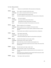
...Check PSU cables. PDR1016 Message Drive is lost . LCD Message Predictive failure on power supply . If the issue persists, see Getting Help. Verify the input power is within the operating requirements for PSU is removed from disk drive bay . Details The controller detected that ...the drive was unable to configure the memory for power supply is not configurable. No memory is detected....
...Check PSU cables. PDR1016 Message Drive is lost . LCD Message Predictive failure on power supply . If the issue persists, see Getting Help. Verify the input power is within the operating requirements for PSU is removed from disk drive bay . Details The controller detected that ...the drive was unable to configure the memory for power supply is not configurable. No memory is detected....

Owner's Manual
Page 131
... more information about system diagnostics. See "Using System Diagnostics" chapter for your system. Warning messages usually interrupt the task and require you run diagnostic tests on the hard drive. Diagnostic Messages The system diagnostic utilities may lose all data on your system. ...Alert messages include information, status, warning, and failure messages for drive, temperature, fan, and power conditions. Warning Messages A warning message alerts you to a possible problem and prompts you may issue messages if you to respond before the...
... more information about system diagnostics. See "Using System Diagnostics" chapter for your system. Warning messages usually interrupt the task and require you run diagnostic tests on the hard drive. Diagnostic Messages The system diagnostic utilities may lose all data on your system. ...Alert messages include information, status, warning, and failure messages for drive, temperature, fan, and power conditions. Warning Messages A warning message alerts you to a possible problem and prompts you may issue messages if you to respond before the...


