
User Manual
Page 4
Be sure to plug into each connector. Connecting Power Cable(s) 4 The connectors on the back of your system have icons indicating which cable to tighten the screws (if any) on the monitor's cable connector. Optional-Connecting the Keyboard, Mouse, and Monitor Figure 2. Connecting Keyboard, Mouse, and Monitor Connect the keyboard, mouse, and monitor (optional). Connecting The Power Cable(s) Figure 3.
Be sure to plug into each connector. Connecting Power Cable(s) 4 The connectors on the back of your system have icons indicating which cable to tighten the screws (if any) on the monitor's cable connector. Optional-Connecting the Keyboard, Mouse, and Monitor Figure 2. Connecting Keyboard, Mouse, and Monitor Connect the keyboard, mouse, and monitor (optional). Connecting The Power Cable(s) Figure 3.

User Manual
Page 5
Plug the other end of the power cable(s) into a grounded electrical outlet or a separate power source such as shown in the illustration, and attach to the monitor. Securing Power Cable(s) Bend the system power cable(s), as an uninterruptible power supply (UPS) or a power distribution unit (PDU). Turning On The System Figure 5. Connect the system's power cable(s) to the system and, if a monitor is used, connect the monitor's power cable to the cable strap. Turning on the System 5 Securing The Power Cable(s) Figure 4.
Plug the other end of the power cable(s) into a grounded electrical outlet or a separate power source such as shown in the illustration, and attach to the monitor. Securing Power Cable(s) Bend the system power cable(s), as an uninterruptible power supply (UPS) or a power distribution unit (PDU). Turning On The System Figure 5. Connect the system's power cable(s) to the system and, if a monitor is used, connect the monitor's power cable to the cable strap. Turning on the System 5 Securing The Power Cable(s) Figure 4.

User Manual
Page 6
... system, see the installation and configuration documentation for your system. Installing the Bezel Install the bezel (optional). You must consider any media of Dell-installed software as BACKUP copies of the page. 6 Be sure the operating system is installed before installing hardware or software not purchased with your... operating system. Installing The Optional Bezel Figure 6. For customers in the United States, call the customer assistance telephone number. Press the power button on supported operating systems, see dell.com/ ossupport. The power indicator should light.
... system, see the installation and configuration documentation for your system. Installing the Bezel Install the bezel (optional). You must consider any media of Dell-installed software as BACKUP copies of the page. 6 Be sure the operating system is installed before installing hardware or software not purchased with your... operating system. Installing The Optional Bezel Figure 6. For customers in the United States, call the customer assistance telephone number. Press the power button on supported operating systems, see dell.com/ ossupport. The power indicator should light.

User Manual
Page 7
... describes how to the operating system, system management software, system updates, and system components that shipped with 1100 W DC power supply unit) 7 NOM Information The following information is available online at support.dell.com/manuals. • The rack documentation included with your rack solution describes how to install your system into a rack...
... describes how to the operating system, system management software, system updates, and system components that shipped with 1100 W DC power supply unit) 7 NOM Information The following information is available online at support.dell.com/manuals. • The rack documentation included with your rack solution describes how to install your system into a rack...

User Manual
Page 8
... Specifications NOTE: The following specifications are only those required by law to support.dell.com. For a complete and current listing of the specifications for your system. supply) 2891 BTU/hr maximum (750 W power supply) 4100 BTU/hr maximum (1100 W power supply) Voltage 100-240 V AC, autoranging, 50/60 Hz NOTE: This system is...
... Specifications NOTE: The following specifications are only those required by law to support.dell.com. For a complete and current listing of the specifications for your system. supply) 2891 BTU/hr maximum (750 W power supply) 4100 BTU/hr maximum (1100 W power supply) Voltage 100-240 V AC, autoranging, 50/60 Hz NOTE: This system is...

User Manual
Page 9
NOTE: For information on supported expanded operating temperature range and configurations, see dell.com/environmental_datasheets. Temperature Operating Continuous operation: 10 °C to 35 °C at 1 °C/300 m above 900 m (1°F per 550 ft). Power Battery Coin-cell battery 3 V CR2032 Lithium coin cell Physical Height Width Depth Ten-hard-drive systems Eight-hard-drive... lb) 9.37 kg (20.66 lb) 8.58 kg (18.92 lb) Environmental NOTE: For additional information about environmental measurements for specific system configurations, see support.dell.com/manuals. 9
NOTE: For information on supported expanded operating temperature range and configurations, see dell.com/environmental_datasheets. Temperature Operating Continuous operation: 10 °C to 35 °C at 1 °C/300 m above 900 m (1°F per 550 ft). Power Battery Coin-cell battery 3 V CR2032 Lithium coin cell Physical Height Width Depth Ten-hard-drive systems Eight-hard-drive... lb) 9.37 kg (20.66 lb) 8.58 kg (18.92 lb) Environmental NOTE: For additional information about environmental measurements for specific system configurations, see support.dell.com/manuals. 9

Owner's Manual
Page 3
......12 Setup Menu...12 View Menu...13 Diagnostic Indicators...13 Hard-Drive Indicator Patterns...14 Back-Panel Features And Indicators...15 NIC Indicator Codes...17 Power Indicator Codes...18 Other Information You May Need...19 2 Using The System Setup And Boot Manager 21 Choosing The System Boot Mode...21 Entering System...
......12 Setup Menu...12 View Menu...13 Diagnostic Indicators...13 Hard-Drive Indicator Patterns...14 Back-Panel Features And Indicators...15 NIC Indicator Codes...17 Power Indicator Codes...18 Other Information You May Need...19 2 Using The System Setup And Boot Manager 21 Choosing The System Boot Mode...21 Entering System...

Owner's Manual
Page 5
... Removing A Processor...67 Installing A Processor...70 Power Supplies...71 Hot Spare Feature...72 Removing An AC Power Supply...72 Installing An AC Power Supply...73 Wiring Instructions For A DC Power Supply...74 Removing A DC Power Supply...76 Installing A DC Power Supply...77 Removing The Power Supply Blank...78 Installing The Power Supply Blank...78 System Battery...78 Replacing...
... Removing A Processor...67 Installing A Processor...70 Power Supplies...71 Hot Spare Feature...72 Removing An AC Power Supply...72 Installing An AC Power Supply...73 Wiring Instructions For A DC Power Supply...74 Removing A DC Power Supply...76 Installing A DC Power Supply...77 Removing The Power Supply Blank...78 Installing The Power Supply Blank...78 System Battery...78 Replacing...

Owner's Manual
Page 6
...A NIC...98 Troubleshooting A Wet System...98 Troubleshooting A Damaged System...99 Troubleshooting The System Battery...100 Troubleshooting Power Supplies...100 Troubleshooting Cooling Problems...100 Troubleshooting Cooling Fans...101 Troubleshooting System Memory...101 Troubleshooting An Internal USB Key...Troubleshooting A Storage Controller...104 Troubleshooting Expansion Cards...105 Troubleshooting Processors...106 5 Using System Diagnostics...107 Dell Online Diagnostics...107 Dell Embedded System Diagnostics...107 When To Use The Embedded System Diagnostics 107 Running The Embedded System ...
...A NIC...98 Troubleshooting A Wet System...98 Troubleshooting A Damaged System...99 Troubleshooting The System Battery...100 Troubleshooting Power Supplies...100 Troubleshooting Cooling Problems...100 Troubleshooting Cooling Fans...101 Troubleshooting System Memory...101 Troubleshooting An Internal USB Key...Troubleshooting A Storage Controller...104 Troubleshooting Expansion Cards...105 Troubleshooting Processors...106 5 Using System Diagnostics...107 Dell Online Diagnostics...107 Dell Embedded System Diagnostics...107 When To Use The Embedded System Diagnostics 107 Running The Embedded System ...

Owner's Manual
Page 9
...One optional SATA DVD-ROM drive or DVD+/-RW drive. 9 The identification buttons on and off. When one of a paper clip. The power button controls the power supply output to do so by qualified support personnel or by the operating system's documentation. To reset the iDRAC (if not disabled in ... to troubleshoot software and device driver errors when running certain operating systems. This button can be pressed using the power button causes the system to perform a graceful shutdown before power to the system. Press to toggle the system ID on the front and back panels can be used to ...
...One optional SATA DVD-ROM drive or DVD+/-RW drive. 9 The identification buttons on and off. When one of a paper clip. The power button controls the power supply output to do so by qualified support personnel or by the operating system's documentation. To reset the iDRAC (if not disabled in ... to troubleshoot software and device driver errors when running certain operating systems. This button can be pressed using the power button causes the system to perform a graceful shutdown before power to the system. Press to toggle the system ID on the front and back panels can be used to ...

Owner's Manual
Page 10
.... 2 System health indicator The system health indicator blinks amber when a system fault is detected. 3 Power-on indicator, power button The power-on indicator lights when the system power is turned on . NOTE: If the system is connected to two 2.5 inch Dell PowerEdge Express Flash devices (PCIe SSDs). Figure 2. Displays system ID, status information, and system error...
.... 2 System health indicator The system health indicator blinks amber when a system fault is detected. 3 Power-on indicator, power button The power-on indicator lights when the system power is turned on . NOTE: If the system is connected to two 2.5 inch Dell PowerEdge Express Flash devices (PCIe SSDs). Figure 2. Displays system ID, status information, and system error...

Owner's Manual
Page 11
Item Indicator, Button, or Icon Description Connector NOTE: On ACPI-compliant operating systems, turning off the system using the power button causes the system to perform a graceful shutdown before power to the system is turned off. 4 NMI button 5 System identification button 6 Mini USB connector 7 Hard drives (10) 8 Information tag Used to troubleshoot software...
Item Indicator, Button, or Icon Description Connector NOTE: On ACPI-compliant operating systems, turning off the system using the power button causes the system to perform a graceful shutdown before power to the system is turned off. 4 NMI button 5 System identification button 6 Mini USB connector 7 Hard drives (10) 8 Information tag Used to troubleshoot software...

Owner's Manual
Page 13
...the system in a simplified user-friendly description. Select Simple to display LCD error messages in BTU/hr or Watts. Power Displays the power output of range, or a failed power supply or voltage regulator). Temperature Displays the temperature of the system in the Set home submenu of the Setup menu....not present if the system is useful when trying to match an LCD message with an LCD display. If it . Re-seat the power supply by removing and reinstalling it is due to a problem with these indicators: Electrical indicator Condition The indicator blinks amber if the ...
...the system in a simplified user-friendly description. Select Simple to display LCD error messages in BTU/hr or Watts. Power Displays the power output of range, or a failed power supply or voltage regulator). Temperature Displays the temperature of the system in the Set home submenu of the Setup menu....not present if the system is useful when trying to match an LCD message with an LCD display. If it . Re-seat the power supply by removing and reinstalling it is due to a problem with these indicators: Electrical indicator Condition The indicator blinks amber if the ...

Owner's Manual
Page 16
... integrated 10/100/1000 Mbps NIC connectors • Two integrated 100 Mbps/1 Gbps/10 Gbps SFP+ connectors 9 PCIe expansion card slot (riser 3) 10 Power supply (PSU1) 11 Power supply (PSU2) Allows you to connect USB devices to connect a PCIe expansion card. Item Indicator, Button, or Icon Description Connector 6 Video connector Allows you...
... integrated 10/100/1000 Mbps NIC connectors • Two integrated 100 Mbps/1 Gbps/10 Gbps SFP+ connectors 9 PCIe expansion card slot (riser 3) 10 Power supply (PSU1) 11 Power supply (PSU2) Allows you to connect USB devices to connect a PCIe expansion card. Item Indicator, Button, or Icon Description Connector 6 Video connector Allows you...
Owner's Manual
Page 17
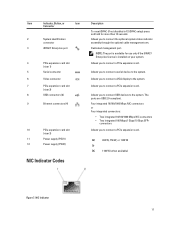
... card slot (riser 1) 5 Serial connector 6 Video connector 7 PCIe expansion card slot (riser 2) 8 USB connectors (2) 9 Ethernet connectors (4) 10 PCIe expansion card slot (riser 3) 11 Power supply (PSU1) 12 Power supply (PSU2) NIC Indicator Codes Description To reset iDRAC (if not disabled in F2 iDRAC setup) press and hold for use only if the...
... card slot (riser 1) 5 Serial connector 6 Video connector 7 PCIe expansion card slot (riser 2) 8 USB connectors (2) 9 Ethernet connectors (4) 10 PCIe expansion card slot (riser 3) 11 Power supply (PSU1) 12 Power supply (PSU2) NIC Indicator Codes Description To reset iDRAC (if not disabled in F2 iDRAC setup) press and hold for use only if the...

Owner's Manual
Page 18
... green Network data is connected to a valid network at less than its maximum port speed (1 Gbps or 10 Gbps). Figure 8. DC power supply status indicator 18 activity indicator Indicator Indicator Code Link and activity indicators are off The NIC is not connected to show whether... power is connected to a valid network at its maximum port speed. AC Power Supply Status Indicator 1. AC power supply status indicator/handle Figure 9. DC Power Supply Status Indicator 1. Link indicator is amber The NIC is being ...
... green Network data is connected to a valid network at less than its maximum port speed (1 Gbps or 10 Gbps). Figure 8. DC power supply status indicator 18 activity indicator Indicator Indicator Code Link and activity indicators are off The NIC is not connected to show whether... power is connected to a valid network at its maximum port speed. AC Power Supply Status Indicator 1. AC power supply status indicator/handle Figure 9. DC Power Supply Status Indicator 1. Link indicator is amber The NIC is being ...

Owner's Manual
Page 19
...change from a High Output configuration to the operating system, system management software, system updates, and system components that the power supply is available online at support.dell.com/manuals. • The rack documentation included with your rack solution describes how to install your system into a ...tools for updates on support.dell.com/manuals and read the updates first because they can result in other installed power supply. CAUTION: Combining AC and DC power supplies is not connected. CAUTION: If two power supplies are used, they must power down the system. Other ...
...change from a High Output configuration to the operating system, system management software, system updates, and system components that the power supply is available online at support.dell.com/manuals. • The rack documentation included with your rack solution describes how to install your system into a ...tools for updates on support.dell.com/manuals and read the updates first because they can result in other installed power supply. CAUTION: Combining AC and DC power supplies is not connected. CAUTION: If two power supplies are used, they must power down the system. Other ...

Owner's Manual
Page 21
... Console Redirection. The following keystrokes provide access to system features during startup: Keystroke Description Enters the System Setup. The Dell LC2 supports systems management features such as operating system deployment, hardware diagnostics, platform updates, and platform configuration, using Console... remove hardware • View the system hardware configuration • Enable or disable integrated devices • Set performance and power management thresholds • Manage system security You can access the System Setup using the: • Standard graphical browser, ...
... Console Redirection. The following keystrokes provide access to system features during startup: Keystroke Description Enters the System Setup. The Dell LC2 supports systems management features such as operating system deployment, hardware diagnostics, platform updates, and platform configuration, using Console... remove hardware • View the system hardware configuration • Enable or disable integrated devices • Set performance and power management thresholds • Manage system security You can access the System Setup using the: • Standard graphical browser, ...
Owner's Manual
Page 23
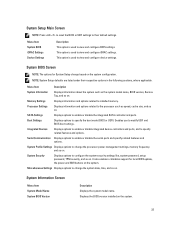
... BIOS or UEFI settings to their respective options in the following sections, where applicable. This option is used to change the processor power management settings, memory frequency, and so on . Miscellaneous Settings Displays options to view and configure BIOS settings. Memory Settings Displays information... model name, BIOS version, Service Tag, and so on . System BIOS Screen NOTE: The options for local BIOS update, the power and NMI buttons on . Integrated Devices Displays options to enable or disable integrated device controllers and ports, and to enable or disable ...
... BIOS or UEFI settings to their respective options in the following sections, where applicable. This option is used to change the processor power management settings, memory frequency, and so on . Miscellaneous Settings Displays options to view and configure BIOS settings. Memory Settings Displays information... model name, BIOS version, Service Tag, and so on . System BIOS Screen NOTE: The options for local BIOS update, the power and NMI buttons on . Integrated Devices Displays options to enable or disable integrated device controllers and ports, and to enable or disable ...

Owner's Manual
Page 28
...the operating system is not installed in all available power states. Allows you to set the DIMM voltage selection. By default, the CPU Power Management option is set to Custom. Allows you to set the CPU power management. CPU Power Management Memory Frequency Turbo Boost C1E C States ... Item Description Intel AES-NI The Intel AES-NI option improves the speed of the options. DAPC is Demand-Based Power Management. DBPM is Dell Active Power Controller. System Password Allows you to set the remote console terminal type. By default, the Redirection After Boot option ...
...the operating system is not installed in all available power states. Allows you to set the DIMM voltage selection. By default, the CPU Power Management option is set to Custom. Allows you to set the CPU power management. CPU Power Management Memory Frequency Turbo Boost C1E C States ... Item Description Intel AES-NI The Intel AES-NI option improves the speed of the options. DAPC is Demand-Based Power Management. DBPM is Dell Active Power Controller. System Password Allows you to set the remote console terminal type. By default, the Redirection After Boot option ...


