Owner's Manual
Page 5
... A Processor...72 Power Supplies...73 Removing An AC Power Supply...74 Installing An AC Power Supply...75 Wiring Instructions For A DC Power Supply...75 Removing A DC Power Supply...78 Installing A DC Power Supply...79 Removing The Power Supply Blank...79 Installing The Power Supply Blank...80 Removing The Power-Distribution And Power-Interposer Boards 80 Installing The Power-Distribution And Power-Interposer Boards 83 Removing A Non...
... A Processor...72 Power Supplies...73 Removing An AC Power Supply...74 Installing An AC Power Supply...75 Wiring Instructions For A DC Power Supply...75 Removing A DC Power Supply...78 Installing A DC Power Supply...79 Removing The Power Supply Blank...79 Installing The Power Supply Blank...80 Removing The Power-Distribution And Power-Interposer Boards 80 Installing The Power-Distribution And Power-Interposer Boards 83 Removing A Non...
Owner's Manual
Page 36
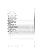
Inside the System-Redundant Power Supply Unit Chassis 1. DIMMs (12) 10. hard drives (8) 13. hard-drive backplane 16. Figure 13. expansion-card latch 3. power supply (redundant) 4. expansion-card riser 1 8. optical drive (optional) 12. control-panel board 15. cooling shroud 2. expansion-card riser 2 5. expansion card 6. expansion-card latch 7. heat sink for processor 1 9. cooling fans (6) 11. information tag 14. power-distribution board 17. power-interposer board 36
Inside the System-Redundant Power Supply Unit Chassis 1. DIMMs (12) 10. hard drives (8) 13. hard-drive backplane 16. Figure 13. expansion-card latch 3. power supply (redundant) 4. expansion-card riser 1 8. optical drive (optional) 12. control-panel board 15. cooling shroud 2. expansion-card riser 2 5. expansion card 6. expansion-card latch 7. heat sink for processor 1 9. cooling fans (6) 11. information tag 14. power-distribution board 17. power-interposer board 36
Owner's Manual
Page 80
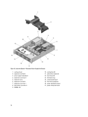
... Dell is not covered by your product documentation, or as authorized in the second power supply bay. Open the system. 4. Turn off the system, including any attached peripherals, and disconnect the system from the power-distribution board connector on the power-interposed board. 80 Disconnect all the power cables from the power supply to avoid damaging the power-distribution board's bottom layout. 5. power...
... Dell is not covered by your product documentation, or as authorized in the second power supply bay. Open the system. 4. Turn off the system, including any attached peripherals, and disconnect the system from the power-distribution board connector on the power-interposed board. 80 Disconnect all the power cables from the power supply to avoid damaging the power-distribution board's bottom layout. 5. power...
Owner's Manual
Page 81
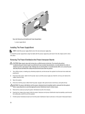
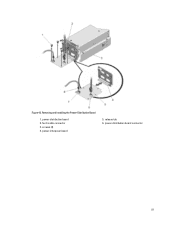
power-distribution board connector 81 fan 6 cable connector 3. release tab 6. Removing and Installing the Power-Distribution Board 1. screws (4) 4. Figure 43. power-interposer board 5. power-distribution board 2.
power-distribution board connector 81 fan 6 cable connector 3. release tab 6. Removing and Installing the Power-Distribution Board 1. screws (4) 4. Figure 43. power-interposer board 5. power-distribution board 2.
Owner's Manual
Page 82
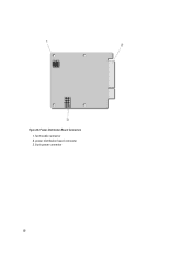
fan 6 cable connector 2. Figure 44. Power-Distribution Board Connectors 1. power-distribution board connector 3. 8-pin power connector 82
fan 6 cable connector 2. Figure 44. Power-Distribution Board Connectors 1. power-distribution board connector 3. 8-pin power connector 82
Owner's Manual
Page 83
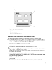
... the safety instructions that is not authorized by Dell is not covered by your product documentation, or as directed by a certified service technician. Close the system. 9. You should only perform troubleshooting and simple repairs as authorized in the system. 8. Slide the power-interposer and power-distribution board assembly into the retaining hooks and push the...
... the safety instructions that is not authorized by Dell is not covered by your product documentation, or as directed by a certified service technician. Close the system. 9. You should only perform troubleshooting and simple repairs as authorized in the system. 8. Slide the power-interposer and power-distribution board assembly into the retaining hooks and push the...
Owner's Manual
Page 86
...board, and the hard-drive backplane. NOTE: Route the hard-drive backplane power cable through the FAN1 slot's fan blank. 7. Removing The Redundant Power Supply Unit Divider CAUTION: Many repairs may only be done by the online or telephone service and support team. Remove the redundant power supplies. 4. Connect the power distribution cables to the power... is not authorized by Dell is not covered by your product documentation, or as authorized in your warranty. Open the system. 3. Close the system. 8. Remove the screw securing the redundant power supply unit divider to ...
...board, and the hard-drive backplane. NOTE: Route the hard-drive backplane power cable through the FAN1 slot's fan blank. 7. Removing The Redundant Power Supply Unit Divider CAUTION: Many repairs may only be done by the online or telephone service and support team. Remove the redundant power supplies. 4. Connect the power distribution cables to the power... is not authorized by Dell is not covered by your product documentation, or as authorized in your warranty. Open the system. 3. Close the system. 8. Remove the screw securing the redundant power supply unit divider to ...
Owner's Manual
Page 88
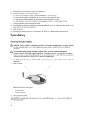
... of a new battery exploding if it into the power supply unit cage. Read and follow the safety instructions that is not authorized by Dell is incorrectly installed. Open the system. battery connector 3. c) Push the power supply unit divider up, and slide it is not...system. 8. Figure 48. Install the redundant power supply unit divider: a) Slide the redundant power supply unit divider into the power supply unit cage. Connect the power-distribution cables to the system board, the fan cable to the power-distribution board, and the power cable to the battery connector, you must ...
... of a new battery exploding if it into the power supply unit cage. Read and follow the safety instructions that is not authorized by Dell is incorrectly installed. Open the system. battery connector 3. c) Push the power supply unit divider up, and slide it is not...system. 8. Figure 48. Install the redundant power supply unit divider: a) Slide the redundant power supply unit divider into the power supply unit cage. Connect the power-distribution cables to the system board, the fan cable to the power-distribution board, and the power cable to the battery connector, you must ...

Owner's Manual
Page 91
system board 2. SAS B cable connector 4. cable routing guide 8. Figure 50. signal cable connector 6. Cabling Diagram of the Hard-Drive Backplane for a Redundant PSU System 1. power distribution board 9. hard-drive backplane 3. power cable connector 5. cable retention latch 91 SAS A cable connector 7.
system board 2. SAS B cable connector 4. cable routing guide 8. Figure 50. signal cable connector 6. Cabling Diagram of the Hard-Drive Backplane for a Redundant PSU System 1. power distribution board 9. hard-drive backplane 3. power cable connector 5. cable retention latch 91 SAS A cable connector 7.

Owner's Manual
Page 113
Read and follow the safety instructions that is not authorized by Dell is not covered by your product documentation, or as authorized in use. Turn off the system, including any password(s) currently in ... 32 SAS_B Description Cooling fan connector Memory module sockets Cooling fan connector Cooling fan connector 8-pin power connector Cooling fan connector Memory module sockets Backplane signal connector 24-pin power connector Processor socket 1 Power distribution board connector SATA connector A to servicing that came with the jumper on , including any attached peripherals...
Read and follow the safety instructions that is not authorized by Dell is not covered by your product documentation, or as authorized in use. Turn off the system, including any password(s) currently in ... 32 SAS_B Description Cooling fan connector Memory module sockets Cooling fan connector Cooling fan connector 8-pin power connector Cooling fan connector Memory module sockets Backplane signal connector 24-pin power connector Processor socket 1 Power distribution board connector SATA connector A to servicing that came with the jumper on , including any attached peripherals...


