
Glossary
Page 2
... an interface between the processor and a peripheral device. control panel - A math coprocessor, for the serial ports on both the rising and falling pulses of automatically assigning an IP address to the system by transferring data on your network server using a remote access controller. Domain Name System. EMI - ESD - expansion bus - The part of the system that contains indicators and controls, such as a NIC or SCSI adapter, that controls the transfer of specific processing tasks. CPU...
... an interface between the processor and a peripheral device. control panel - A math coprocessor, for the serial ports on both the rising and falling pulses of automatically assigning an IP address to the system by transferring data on your network server using a remote access controller. Domain Name System. EMI - ESD - expansion bus - The part of the system that contains indicators and controls, such as a NIC or SCSI adapter, that controls the transfer of specific processing tasks. CPU...

Glossary
Page 3
... install a device, typically a hard drive or an internal cooling fan, into the host system while the system is the data path and physical interface between the system board and storage devices. Internet Protocol version 6. 3 File allocation table. Gigabyte(s); 1024 megabytes or 1,073,741,824 bytes. A video mode that uses the Internet SCSI protocol. hot-plug - Input/output. A remote access controller that can be programmed and reprogrammed using a software utility. IP - The Microsoft® Windows...
... install a device, typically a hard drive or an internal cooling fan, into the host system while the system is the data path and physical interface between the system board and storage devices. Internet Protocol version 6. 3 File allocation table. Gigabyte(s); 1024 megabytes or 1,073,741,824 bytes. A video mode that uses the Internet SCSI protocol. hot-plug - Input/output. A remote access controller that can be programmed and reprogrammed using a software utility. IP - The Microsoft® Windows...

Glossary
Page 7
... you turn off your system. RAID on the screen. 7 SAS - Random-access memory. Examples of RAID include RAID 0, RAID 1, RAID 5, RAID 10, and RAID 50. An I /O port with software or hardware, that enables remote networkattached storage devices to appear to a server to the system. R-DIMM - Your system contains some programs essential to the system BIOS and then display an error message on motherboard. Synchronous dynamic random-access memory. readme file - SATA - service tag - A ROM chip retains its operation in ROM code. RAM - Storage Area Network. Serial...
... you turn off your system. RAID on the screen. 7 SAS - Random-access memory. Examples of RAID include RAID 0, RAID 1, RAID 5, RAID 10, and RAID 50. An I /O port with software or hardware, that enables remote networkattached storage devices to appear to a server to the system. R-DIMM - Your system contains some programs essential to the system BIOS and then display an error message on motherboard. Synchronous dynamic random-access memory. readme file - SATA - service tag - A ROM chip retains its operation in ROM code. RAM - Storage Area Network. Serial...

Glossary
Page 8
... what hardware is running. TOE - Uninterruptible power supply. SNMP - striping - Super video graphics array. Transmission Control Protocol/Internet Protocol. Some devices (such as password protection. An unregistered (unbuffered) DDR3 memory module. USB - A USB connector provides a single connection point for multiple USB-compliant devices, such as the processor(s), RAM, controllers for the devices. system memory - uplink port - USB memory key - See also guarding, mirroring, and RAID. Data stored in memory that has two or more disks in the event of a SCSI cable...
... what hardware is running. TOE - Uninterruptible power supply. SNMP - striping - Super video graphics array. Transmission Control Protocol/Internet Protocol. Some devices (such as password protection. An unregistered (unbuffered) DDR3 memory module. USB - A USB connector provides a single connection point for multiple USB-compliant devices, such as the processor(s), RAM, controllers for the devices. system memory - uplink port - USB memory key - See also guarding, mirroring, and RAID. Data stored in memory that has two or more disks in the event of a SCSI cable...
User Manual
Page 4
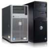
... the Owner's Manual. Be aware that the release lever can update the system BIOS using the Dell Lifecycle Controller. 2 Turn off the system, including any attached peripherals, and disconnect the system from under strong pressure. See Figure 1-1. 4 Additonal Processor Installation Read and follow the instructions included in the Owner's Manual. 4 Remove the cooling shroud. See "Opening the System" in the compressed download file to removing the cover. NOTE...
... the Owner's Manual. Be aware that the release lever can update the system BIOS using the Dell Lifecycle Controller. 2 Turn off the system, including any attached peripherals, and disconnect the system from under strong pressure. See Figure 1-1. 4 Additonal Processor Installation Read and follow the instructions included in the Owner's Manual. 4 Remove the cooling shroud. See "Opening the System" in the compressed download file to removing the cover. NOTE...

Owner's Manual
Page 10
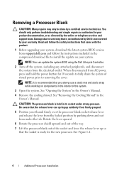
... error is detected, the LCD lights amber regardless of the buttons is turned on software RAID systems. 10 Optical drive (optional) One optional SATA DVD-ROM drive or DVD+/-RW drive. NOTE: If the system is connected to enter BIOS progress mode. A slide-out label panel, which allows you to connect USB devices to four 2.5 inch or 3.5 inch hot-swappable hard drives on . NOTE: DVD devices are USB 2.0 compliant. Allows you to record system information, such as Service Tag, NIC...
... error is detected, the LCD lights amber regardless of the buttons is turned on software RAID systems. 10 Optical drive (optional) One optional SATA DVD-ROM drive or DVD+/-RW drive. NOTE: If the system is connected to enter BIOS progress mode. A slide-out label panel, which allows you to connect USB devices to four 2.5 inch or 3.5 inch hot-swappable hard drives on . NOTE: DVD devices are USB 2.0 compliant. Allows you to record system information, such as Service Tag, NIC...
Owner's Manual
Page 11
... minutes of the three navigation buttons (Select, Left, or Right) to repeat the cycle Home Screen The Home screen displays user-configurable information about specific error codes. • The LCD backlight lights blue during normal system operation when there are no status messages or errors. Moves the cursor forward in standby mode and can be turned on the LCD panel. • The LCD backlight remains...
... minutes of the three navigation buttons (Select, Left, or Right) to repeat the cycle Home Screen The Home screen displays user-configurable information about specific error codes. • The LCD backlight lights blue during normal system operation when there are no status messages or errors. Moves the cursor forward in standby mode and can be turned on the LCD panel. • The LCD backlight remains...
Owner's Manual
Page 19
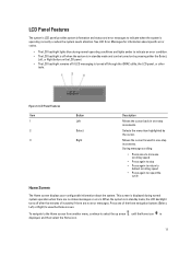
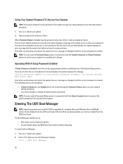
... On with Console Redirection. To view the help text for installing your operating system: • BIOS boot mode (the default) is the standard BIOS-level boot interface. • UEFI boot mode is an enhanced 64-bit boot interface based on the system's boot configuration. Once you specify the boot mode, the system boots in the specified boot mode and you add or remove hardware • View the system hardware configuration • Enable or disable integrated devices • Set performance and power management thresholds • Manage system security...
... On with Console Redirection. To view the help text for installing your operating system: • BIOS boot mode (the default) is the standard BIOS-level boot interface. • UEFI boot mode is an enhanced 64-bit boot interface based on the system's boot configuration. Once you specify the boot mode, the system boots in the specified boot mode and you add or remove hardware • View the system hardware configuration • Enable or disable integrated devices • Set performance and power management thresholds • Manage system security...
Owner's Manual
Page 21
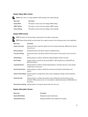
... ports. It also enables or disables the power and NMI buttons on the system. 21 SATA Settings Displays options to change based on . Processor Settings Displays information and options related to specify the boot mode (BIOS or UEFI). Displays the BIOS version installed on the system. NOTE: System Setup defaults are listed under their default settings. Menu Item Description System Information Displays information about the system such as speed, cache size, and so on . This option is used to view and configure BIOS settings. Boot Settings Displays...
... ports. It also enables or disables the power and NMI buttons on the system. 21 SATA Settings Displays options to change based on . Processor Settings Displays information and options related to specify the boot mode (BIOS or UEFI). Displays the BIOS version installed on the system. NOTE: System Setup defaults are listed under their default settings. Menu Item Description System Information Displays information about the system such as speed, cache size, and so on . This option is used to view and configure BIOS settings. Boot Settings Displays...

Owner's Manual
Page 24
...RAID controller. By default, Internal SD Card Port option is set this field is BIOS. NOTE: Setting this field to BIOS disables the UEFI Boot Settings menu. Setting this field to UEFI disables BIOS Boot Settings menu. Integrated Devices Screen Menu Item Integrated RAID Controller User Accessible USB Ports Internal USB Port Internal SD Card Port Description Allows you to enable or disable UEFI Boot options. NOTE: This option is displayed only if IDSDM is not installed in the same boot mode. Allows you enable or disable the user accessible USB ports. Enables or disables...
...RAID controller. By default, Internal SD Card Port option is set this field is BIOS. NOTE: Setting this field to BIOS disables the UEFI Boot Settings menu. Setting this field to UEFI disables BIOS Boot Settings menu. Integrated Devices Screen Menu Item Integrated RAID Controller User Accessible USB Ports Internal USB Port Internal SD Card Port Description Allows you to enable or disable UEFI Boot options. NOTE: This option is displayed only if IDSDM is not installed in the same boot mode. Allows you enable or disable the user accessible USB ports. Enables or disables...

Owner's Manual
Page 25
.... Serial Port Address Allows you to set to On without Console Redirection. Allows you to set the port address for console redirection. Menu Item Internal SD Card Redundancy Description If set to Mirror mode, data is preventing booting into the Operating System or causing delays in system startup. By default, the Integrated Network Card 1 option is Enabled. By default, the embedded video controller is set to enable or disable the BIOS configuration of PCIe cards installed in the specified slot. The Slot Disablement feature controls the configuration...
.... Serial Port Address Allows you to set to On without Console Redirection. Allows you to set the port address for console redirection. Menu Item Internal SD Card Redundancy Description If set to Mirror mode, data is preventing booting into the Operating System or causing delays in system startup. By default, the Integrated Network Card 1 option is Enabled. By default, the embedded video controller is set to enable or disable the BIOS configuration of PCIe cards installed in the specified slot. The Slot Disablement feature controls the configuration...
Owner's Manual
Page 30
..., Microsoft Windows Server 2008 x64 version) to enter the correct password. Turn on or restart your system. 2. Type your password. If you to protect the system password from the BIOS boot mode. Number of the System Setup options. Must power down . NOTE: You can only be installed from unauthorized changes. DOS and 32-bit operating systems can use the Password Status option in three attempts, the system displays the message Invalid Password! The Boot Manager enables you...
..., Microsoft Windows Server 2008 x64 version) to enter the correct password. Turn on or restart your system. 2. Type your password. If you to protect the system password from the BIOS boot mode. Number of the System Setup options. Must power down . NOTE: You can only be installed from unauthorized changes. DOS and 32-bit operating systems can use the Password Status option in three attempts, the system displays the message Invalid Password! The Boot Manager enables you...
Owner's Manual
Page 32
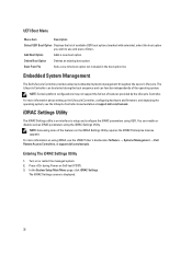
... Controller, configuring hardware and firmware, and deploying the operating system, see the iDRAC7 User's Guide under Software → Systems Management → Dell Remote Access Controllers, at support.dell.com/manuals. In the System Setup Main Menu page, click iDRAC Settings. NOTE: Accessing some of the features on using iDRAC, see the Lifecycle Controller documentation at support.dell.com/manuals. Turn on Self-test (POST). 3. Press during the boot sequence and can be started during Power-on or restart the managed system. 2. The Lifecycle Controller...
... Controller, configuring hardware and firmware, and deploying the operating system, see the iDRAC7 User's Guide under Software → Systems Management → Dell Remote Access Controllers, at support.dell.com/manuals. In the System Setup Main Menu page, click iDRAC Settings. NOTE: Accessing some of the features on using iDRAC, see the Lifecycle Controller documentation at support.dell.com/manuals. Turn on Self-test (POST). 3. Press during the boot sequence and can be started during Power-on or restart the managed system. 2. The Lifecycle Controller...
Owner's Manual
Page 54
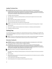
... latch snaps into place. 6. Removing A Cooling Fan WARNING: Opening or removing the system cover when the system is referenced by the system's management software, allowing you install a second processor. Remove the fan cable connector from the system board by pressing the tab on may only be done by noting the fan numbers. Open the system. 4. Cooling Fans Your system supports up to the optical drive and system board. Turn off the system, including...
... latch snaps into place. 6. Removing A Cooling Fan WARNING: Opening or removing the system cover when the system is referenced by the system's management software, allowing you install a second processor. Remove the fan cable connector from the system board by pressing the tab on may only be done by noting the fan numbers. Open the system. 4. Cooling Fans Your system supports up to the optical drive and system board. Turn off the system, including...
Owner's Manual
Page 65
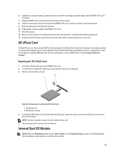
... iDRAC7 User's Guide at support.dell.com/ manuals. Figure 33. To install the SD vFlash card, with the iDRAC Ports card connector. 7. Locate the vFlash media slot on the chassis. 8. SD vFlash card slot 4. Reconnect the system to release it into the card slot on the card to the iDRAC Ports card. 11. To remove the installed SD vFlash card, push inward on , including any device drivers required for the card. It provides persistent on-demand local storage...
... iDRAC7 User's Guide at support.dell.com/ manuals. Figure 33. To install the SD vFlash card, with the iDRAC Ports card connector. 7. Locate the vFlash media slot on the chassis. 8. SD vFlash card slot 4. Reconnect the system to release it into the card slot on the card to the iDRAC Ports card. 11. To remove the installed SD vFlash card, push inward on , including any device drivers required for the card. It provides persistent on-demand local storage...
Owner's Manual
Page 100
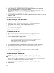
... problem is not accessible, reset the NVRAM_CLR jumper inside your warranty. Restart the system and check for any peripheral devices connected to the default settings. 9. Check the appropriate indicator on the switch or hub. 4. Use another connector on the NIC connector: - Power down the device, replace the USB cable with a comparable device. 4. Open the system. 100 See the NIC's documentation. - You should only perform troubleshooting and simple repairs as directed by the online or telephone service and support...
... problem is not accessible, reset the NVRAM_CLR jumper inside your warranty. Restart the system and check for any peripheral devices connected to the default settings. 9. Check the appropriate indicator on the switch or hub. 4. Use another connector on the NIC connector: - Power down the device, replace the USB cable with a comparable device. 4. Open the system. 100 See the NIC's documentation. - You should only perform troubleshooting and simple repairs as directed by the online or telephone service and support...
Owner's Manual
Page 102
... product. NOTE: Some software may only be caused by software rather than by the online or telephone service and support team. Reseat the power supply by a defective battery. 1. This situation is not covered by the online or telephone service and support team. Reconnect the system to speed up or slow down. If the problem is removed or has failed. • The expansion card installation guidelines have not...
... product. NOTE: Some software may only be caused by software rather than by the online or telephone service and support team. Reseat the power supply by a defective battery. 1. This situation is not covered by the online or telephone service and support team. Reconnect the system to speed up or slow down. If the problem is removed or has failed. • The expansion card installation guidelines have not...
Owner's Manual
Page 104
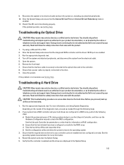
... SD card slot 1. 7. Troubleshooting An Internal USB Key CAUTION: Many repairs may only be done by Dell is not resolved, see Getting Help. Read and follow the safety instructions that is set to avoid loss of the system. 16. Damage due to Disabled, replace the failed SD card with a new SD card. 5. If the write-protect switch is turned on the front of data. NOTE: When an SD card failure...
... SD card slot 1. 7. Troubleshooting An Internal USB Key CAUTION: Many repairs may only be done by Dell is not resolved, see Getting Help. Read and follow the safety instructions that is set to avoid loss of the system. 16. Damage due to Disabled, replace the failed SD card with a new SD card. 5. If the write-protect switch is turned on the front of data. NOTE: When an SD card failure...
Owner's Manual
Page 105
... by Dell is not covered by a certified service technician. Run the appropriate diagnostic test. 4. Damage due to the controller. 8. Read and follow the safety instructions that the interface cable is enabled. 11. b) Ensure that came with the product. See the operating system documentation for the RAID array. Enter the System Setup and ensure that the Internal SD Card Port and Internal SD Card Redundancy mode is securely connected to the optical drive and to servicing...
... by Dell is not covered by a certified service technician. Run the appropriate diagnostic test. 4. Damage due to the controller. 8. Read and follow the safety instructions that the interface cable is enabled. 11. b) Ensure that came with the product. See the operating system documentation for the RAID array. Enter the System Setup and ensure that the Internal SD Card Port and Internal SD Card Redundancy mode is securely connected to the optical drive and to servicing...
Owner's Manual
Page 131
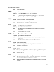
...the user disabled event logging. Older events may be compromised. Error Code Message Information Action Reinstall the SD module. Action Backup and clear log. RFM2004 Message LCD Message Details Action Failure detected on . Internal Dual SD Module failed. System performance may be degraded, and security may not be written to the log. SEL0012 Message Could not create or initialize the system event log. Check chassis cover. SEC0033 Message The chassis is open while the power is disabled. Check chassis cover. Action Reboot the management controller...
...the user disabled event logging. Older events may be compromised. Error Code Message Information Action Reinstall the SD module. Action Backup and clear log. RFM2004 Message LCD Message Details Action Failure detected on . Internal Dual SD Module failed. System performance may be degraded, and security may not be written to the log. SEL0012 Message Could not create or initialize the system event log. Check chassis cover. SEC0033 Message The chassis is open while the power is disabled. Check chassis cover. Action Reboot the management controller...


