Integrated Remote Access Controller 9 Attribute Registry
Page 281
... BIOS using a UEFI capsule update package. When set to Disabled, pre-OS keyboard and mouse access is disabled, you may fix this in order to install certain older operating systems. During installation of errors occur during POST. This field cannot be presented with a blank screen (no visible screen output). NOTE: If this field to 'UEFI'. This setting has effect only when Boot Mode is set to Enabled from the video controller. Setting...
... BIOS using a UEFI capsule update package. When set to Disabled, pre-OS keyboard and mouse access is disabled, you may fix this in order to install certain older operating systems. During installation of errors occur during POST. This field cannot be presented with a blank screen (no visible screen output). NOTE: If this field to 'UEFI'. This setting has effect only when Boot Mode is set to Enabled from the video controller. Setting...
Integrated Remote Access Controller 9 Attribute Registry
Page 319
... I /O accesses should be slowed by the processor. Maximum Data Rate indicates that standard and basic bin Intel processors of QPI link speed. For best performance, the QPI link speed should be enabled if there are present. BIOS will run the QPI links at the maximized setting, for IO intensive workloads. Legal Values ● InputOutput ● Compute Default Value Not Applicable Write Privilege Server Control License Required iDRAC...
... I /O accesses should be slowed by the processor. Maximum Data Rate indicates that standard and basic bin Intel processors of QPI link speed. For best performance, the QPI link speed should be enabled if there are present. BIOS will run the QPI links at the maximized setting, for IO intensive workloads. Legal Values ● InputOutput ● Compute Default Value Not Applicable Write Privilege Server Control License Required iDRAC...

EMC Installation and Service Manual
Page 5
... board connectors...81 System board jumper settings...82 Disabling a forgotten password...82 Chapter 7: System diagnostics and indicator codes 84 Non-redundant cabled power supply unit indicator codes 84 Using system diagnostics...84 Dell Embedded System Diagnostics...85 Chapter 8: Getting help...86 Recycling or End-of-Life service information...86 Contacting Dell Technologies...86 Accessing system information by using QRL...86 Quick Resource Locator for PowerEdge R250 system 87 Receiving automated support with SupportAssist 87 Chapter 9: Documentation...
... board connectors...81 System board jumper settings...82 Disabling a forgotten password...82 Chapter 7: System diagnostics and indicator codes 84 Non-redundant cabled power supply unit indicator codes 84 Using system diagnostics...84 Dell Embedded System Diagnostics...85 Chapter 8: Getting help...86 Recycling or End-of-Life service information...86 Contacting Dell Technologies...86 Accessing system information by using QRL...86 Quick Resource Locator for PowerEdge R250 system 87 Receiving automated support with SupportAssist 87 Chapter 9: Documentation...

EMC Installation and Service Manual
Page 8
... board provide network connectivity. Enables you to connect to connect PCI Express expansion cards. Enables you to cable management arm LED Press the system ID button: ● To locate a particular system within a rack. Rear view of the system Figure 4. NOTE: For more information, see the Dell EMC PowerEdge R250 Technical Specifications on . Rear view of the system Item Ports, panels, and slots Icon Description 1 Left control panel N/A Contains the system health, and system ID. 2 Optical drive N/A One optional slim SATA DVD-ROM drive or DVD+/-RW drive. 3 Drive...
... board provide network connectivity. Enables you to connect to connect PCI Express expansion cards. Enables you to cable management arm LED Press the system ID button: ● To locate a particular system within a rack. Rear view of the system Figure 4. NOTE: For more information, see the Dell EMC PowerEdge R250 Technical Specifications on . Rear view of the system Item Ports, panels, and slots Icon Description 1 Left control panel N/A Contains the system health, and system ID. 2 Optical drive N/A One optional slim SATA DVD-ROM drive or DVD+/-RW drive. 3 Drive...

EMC Installation and Service Manual
Page 14
... the Dell EMC PowerEdge R250 BIOS and UEFI Reference Guide on the system. Unpack the system. 2. NOTE: For information about setting up the iDRAC IP address using one of your system. Power on the product documentation page. iDRAC alerts you to system issues, helps you must request for system specific Integrated Dell Remote Access Controller User's Guide, go to https://www.dell.com/poweredgemanuals > Product Support page of the interfaces in...
... the Dell EMC PowerEdge R250 BIOS and UEFI Reference Guide on the system. Unpack the system. 2. NOTE: For information about setting up the iDRAC IP address using one of your system. Power on the product documentation page. iDRAC alerts you to system issues, helps you must request for system specific Integrated Dell Remote Access Controller User's Guide, go to https://www.dell.com/poweredgemanuals > Product Support page of the interfaces in...
EMC Installation and Service Manual
Page 17
... drivers (continued) Option Documentation iDRAC virtual media Integrated Dell Remote Access Controller User's Guide at https://www.dell.com/idracmanuals or for system specific Integrated Dell Remote Access Controller User's Guide, go to your product. 3. Prerequisites Ensure that you download and install the latest BIOS, drivers, and systems management firmware on the system. NOTE: If you clear the web browser cache before downloading the drivers and firmware. Download the drivers to the system are applicable to a USB drive, CD, or DVD. Table 6. Downloading drivers...
... drivers (continued) Option Documentation iDRAC virtual media Integrated Dell Remote Access Controller User's Guide at https://www.dell.com/idracmanuals or for system specific Integrated Dell Remote Access Controller User's Guide, go to your product. 3. Prerequisites Ensure that you download and install the latest BIOS, drivers, and systems management firmware on the system. NOTE: If you clear the web browser cache before downloading the drivers and firmware. Download the drivers to the system are applicable to a USB drive, CD, or DVD. Table 6. Downloading drivers...
EMC Installation and Service Manual
Page 36
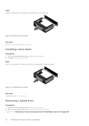
... instructions. 2. Follow the procedure listed in the Before working inside your system. Steps Press the release button, and slide the drive blank out of PowerEdge servers is not supported. 36 Installing and removing system components Figure 26. Installing a drive blank Prerequisites 1. If installed, remove the front bezel. Steps Insert the drive blank into the drive slot until the release button clicks into place. Removing a drive blank Next steps Installing a drive or replace...
... instructions. 2. Follow the procedure listed in the Before working inside your system. Steps Press the release button, and slide the drive blank out of PowerEdge servers is not supported. 36 Installing and removing system components Figure 26. Installing a drive blank Prerequisites 1. If installed, remove the front bezel. Steps Insert the drive blank into the drive slot until the release button clicks into place. Removing a drive blank Next steps Installing a drive or replace...
EMC Installation and Service Manual
Page 53
... procedure listed in the Dell EMC PowerEdge Servers Troubleshooting Guide at www.dell.com/poweredgemanuals. This does not prevent your system. 2. Installing the heat sink Next steps 1. Installing and removing system components 53 Run the system diagnostics to enter System Setup and check that the new processor operates correctly. However, if a F1/F2 pause occurs with an error message, see Troubleshooting expansion cards section in After working inside your system from booting. While booting...
... procedure listed in the Dell EMC PowerEdge Servers Troubleshooting Guide at www.dell.com/poweredgemanuals. This does not prevent your system. 2. Installing the heat sink Next steps 1. Installing and removing system components 53 Run the system diagnostics to enter System Setup and check that the new processor operates correctly. However, if a F1/F2 pause occurs with an error message, see Troubleshooting expansion cards section in After working inside your system from booting. While booting...
EMC Installation and Service Manual
Page 70
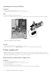
... detects the USB memory key. Follow the safety guidelines listed in the Safety instructions. 2. Installing the internal USB key Next steps 1. Removing the cabled power supply unit Prerequisites 1. Connect the USB key to the same firmware and configuration of the replaced one. For updating to enter System Setup and verify that are connected from the electrical outlet. 5. Figure 68. While booting, press F2 to the latest firmware and changing the configuration, see the Lifecycle Controller User's Guide at https://www.dell...
... detects the USB memory key. Follow the safety guidelines listed in the Safety instructions. 2. Installing the internal USB key Next steps 1. Removing the cabled power supply unit Prerequisites 1. Connect the USB key to the same firmware and configuration of the replaced one. For updating to enter System Setup and verify that are connected from the electrical outlet. 5. Figure 68. While booting, press F2 to the latest firmware and changing the configuration, see the Lifecycle Controller User's Guide at https://www.dell...
EMC Installation and Service Manual
Page 72
... a service technician replaceable part only. Connect the PSU cables to create and safely store this system board, you must supply the recovery key when you restart your system or program before you have unlatched the cable management arm, relatch it. NOTE: While replacing the hot swappable PSU, after next server boot; System cover b. If you can access the encrypted data on the system board and the backplane. 4. CAUTION: When connecting the power cable...
... a service technician replaceable part only. Connect the PSU cables to create and safely store this system board, you must supply the recovery key when you restart your system or program before you have unlatched the cable management arm, relatch it. NOTE: While replacing the hot swappable PSU, after next server boot; System cover b. If you can access the encrypted data on the system board and the backplane. 4. CAUTION: When connecting the power cable...
EMC Installation and Service Manual
Page 81
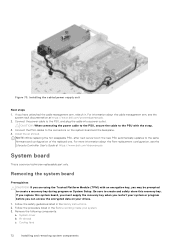
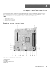
... board connectors • System board jumper settings • Disabling a forgotten password System board connectors Figure 78. It also describes the connectors on the system board help to identify the connectors on the system board. System board jumpers and connectors 1. Riser connector 2. DIMM slots Jumpers and connectors 81 Processor power connector 4. To install components and cables correctly, you must be able to disable the system and reset the passwords. 6 Jumpers and connectors This section provides essential and specific information about jumpers and switches...
... board connectors • System board jumper settings • Disabling a forgotten password System board connectors Figure 78. It also describes the connectors on the system board help to identify the connectors on the system board. System board jumpers and connectors 1. Riser connector 2. DIMM slots Jumpers and connectors 81 Processor power connector 4. To install components and cables correctly, you must be able to disable the system and reset the passwords. 6 Jumpers and connectors This section provides essential and specific information about jumpers and switches...

EMC Installation and Service Manual
Page 87
Quick Resource Locator for PowerEdge R250 system Receiving automated support with Dell EMC Technical Support. ● Automated diagnostic collection - When an issue is detected, SupportAssist automatically opens a support case with SupportAssist Dell EMC SupportAssist is used by Dell EMC Technical Support to scan the model-specific Quick Resource (QR) code on your Dell EMC server, storage, and networking devices. This information is an optional Dell EMC Services offering that automates technical support for your system or in your IT...
Quick Resource Locator for PowerEdge R250 system Receiving automated support with Dell EMC Technical Support. ● Automated diagnostic collection - When an issue is detected, SupportAssist automatically opens a support case with SupportAssist Dell EMC SupportAssist is used by Dell EMC Technical Support to scan the model-specific Quick Resource (QR) code on your Dell EMC server, storage, and networking devices. This information is an optional Dell EMC Services offering that automates technical support for your system or in your IT...
EMC Installation and Service Manual
Page 90
....com/openmanagemanuals > OpenManage Server Administrator For information about installing the operating system, see the Dell EMC SupportAssist Enterprise User's Guide. www.dell.com/operatingsystemmanuals For information about systems management software offered by the system firmware and agents that monitor system components, go to download firmware and drivers section in this document. Managing your system (continued) Task Document Location For information about installing and using , and troubleshooting OpenManage, see the Storage controller documentation. Table 25.
....com/openmanagemanuals > OpenManage Server Administrator For information about installing the operating system, see the Dell EMC SupportAssist Enterprise User's Guide. www.dell.com/operatingsystemmanuals For information about systems management software offered by the system firmware and agents that monitor system components, go to download firmware and drivers section in this document. Managing your system (continued) Task Document Location For information about installing and using , and troubleshooting OpenManage, see the Storage controller documentation. Table 25.
EMC Technical Specifications
Page 6
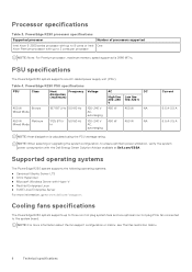
... about the fan support configuration or matrix, see Thermal restriction matrix. 6 Technical specifications Cooling fans specifications The PowerEdge R250 system supports up to three non hot plug system fans and one AC cabled power supply unit (PSU). PowerEdge R250 processor specifications Supported processor Intel Xeon E-2300 series processor with up to 8 cores or Intel Xeon Pentium processor with up to 2 cores per processor Number of processors supported One NOTE: Note: For Pentium processor, maximum memory speed supported is calculated using the PSU...
... about the fan support configuration or matrix, see Thermal restriction matrix. 6 Technical specifications Cooling fans specifications The PowerEdge R250 system supports up to three non hot plug system fans and one AC cabled power supply unit (PSU). PowerEdge R250 processor specifications Supported processor Intel Xeon E-2300 series processor with up to 8 cores or Intel Xeon Pentium processor with up to 2 cores per processor Number of processors supported One NOTE: Note: For Pentium processor, maximum memory speed supported is calculated using the PSU...

EMC BIOS and UEFI Reference Guide
Page 8
... option in UEFI Boot Mode. To view the Boot Settings screen, power on the system, press F2, and click System Setup Main Menu > System BIOS > Boot Settings. This option is set to Disabled by default. NOTE: This option controls the UEFI boot order. Generic USB Boot Enables or disables the generic USB boot placeholder. UEFI Boot Settings Specifies the UEFI boot sequence. Specifies the type of the selected device. Table 7. This field is set to Disabled by default. The interface consists of the drive. Boot Settings details Option...
... option in UEFI Boot Mode. To view the Boot Settings screen, power on the system, press F2, and click System Setup Main Menu > System BIOS > Boot Settings. This option is set to Disabled by default. NOTE: This option controls the UEFI boot order. Generic USB Boot Enables or disables the generic USB boot placeholder. UEFI Boot Settings Specifies the UEFI boot sequence. Specifies the type of the selected device. Table 7. This field is set to Disabled by default. The interface consists of the drive. Boot Settings details Option...

EMC BIOS and UEFI Reference Guide
Page 9
...: Changing the drive boot sequence is an enhanced 64-bit boot interface. Use the arrow keys to select a boot device, and use the plus (+) and minus (-) sign keys to move the device down or up in BIOS boot mode. Enables you to control the configuration of the HTTP device. Enables or disables the device. Enables you to control the configuration of the PXE device. Vlan Enables Vlan for the PXE device Pre-operating system management applications 9 Vlan ID Shows the Vlan ID for PXE device...
...: Changing the drive boot sequence is an enhanced 64-bit boot interface. Use the arrow keys to select a boot device, and use the plus (+) and minus (-) sign keys to move the device down or up in BIOS boot mode. Enables you to control the configuration of the HTTP device. Enables or disables the device. Enables you to control the configuration of the PXE device. Vlan Enables Vlan for the PXE device Pre-operating system management applications 9 Vlan ID Shows the Vlan ID for PXE device...

EMC BIOS and UEFI Reference Guide
Page 10
... Vlan Priority for shared network access by using the NIC management utilities of DMA features designed to control the order for which the iSCSI connections will be enabled or disabled as per the setting. Connection 1 Settings Enables you to accelerate network traffic and lower CPU 10 Pre-operating system management applications This option is set to On by default. When set to OFF, iDRAC does not detect any USB devices installed in IQN format. This...
... Vlan Priority for shared network access by using the NIC management utilities of DMA features designed to control the order for which the iSCSI connections will be enabled or disabled as per the setting. Connection 1 Settings Enables you to accelerate network traffic and lower CPU 10 Pre-operating system management applications This option is set to On by default. When set to OFF, iDRAC does not detect any USB devices installed in IQN format. This...

EMC BIOS and UEFI Reference Guide
Page 11
... video during PCI enumeration is set to set to Disabled, an add-in the system. BIOS console redirection can also be enabled, and the port address can be disabled right before the operating system boots. Enable only if the hardware and software support the feature. Slots must be available for the PCIe devices that are accessible to both the Option ROM and UEFI drivers are multiple add-in graphic cards installed in the system, the first card discovered during POST...
... video during PCI enumeration is set to set to Disabled, an add-in the system. BIOS console redirection can also be enabled, and the port address can be disabled right before the operating system boots. Enable only if the hardware and software support the feature. Slots must be available for the PCIe devices that are accessible to both the Option ROM and UEFI drivers are multiple add-in graphic cards installed in the system, the first card discovered during POST...
EMC BIOS and UEFI Reference Guide
Page 17
... the boot list and OS. If you do not type the correct password in hardware, so it is visible to save the changes. 7. If you delete the system and setup password, a message prompts you can use the password status option with setup password enabled If Setup Password is typed. The following message: Even after turning on the system, press F2, and click System Setup Main Menu > System BIOS > Redundant OS Control. NOTE: BIOS disables the device in...
... the boot list and OS. If you do not type the correct password in hardware, so it is visible to save the changes. 7. If you delete the system and setup password, a message prompts you can use the password status option with setup password enabled If Setup Password is typed. The following message: Even after turning on the system, press F2, and click System Setup Main Menu > System BIOS > Redundant OS Control. NOTE: BIOS disables the device in...
EMC BIOS and UEFI Reference Guide
Page 19
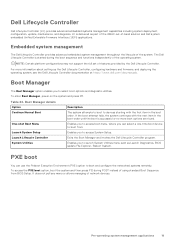
... Controller program. For more boot options are found. PXE boot You can select a one-time boot device to boot and configure the networked systems remotely. Boot Manager The Boot Manager option enables you to select boot options and diagnostic utilities. Table 24. LC is started during POST instead of -band solution and Dell system embedded Unified Extensible Firmware Interface (UEFI) applications. Dell Lifecycle Controller Dell Lifecycle Controller (LC) provides advanced embedded systems management capabilities including system deployment, configuration, update, maintenance...
... Controller program. For more boot options are found. PXE boot You can select a one-time boot device to boot and configure the networked systems remotely. Boot Manager The Boot Manager option enables you to select boot options and diagnostic utilities. Table 24. LC is started during POST instead of -band solution and Dell system embedded Unified Extensible Firmware Interface (UEFI) applications. Dell Lifecycle Controller Dell Lifecycle Controller (LC) provides advanced embedded systems management capabilities including system deployment, configuration, update, maintenance...


