
Getting Started Guide
Page 12
... USB Video eSATA Front Video USB Internal USB Two RJ-45 (for integrated 1 GB NICs) 9-pin, DTE, 16550-compatible Two 4-pin, USB 2.0-compliant 15-pin VGA One 7-pin connector 15-pin VGA Two 4-pin, USB 2.0-compliant Two 4-pin, USB 2.0-compliant ...
... USB Video eSATA Front Video USB Internal USB Two RJ-45 (for integrated 1 GB NICs) 9-pin, DTE, 16550-compatible Two 4-pin, USB 2.0-compliant 15-pin VGA One 7-pin connector 15-pin VGA Two 4-pin, USB 2.0-compliant Two 4-pin, USB 2.0-compliant ...

Owner's Manual
Page 3
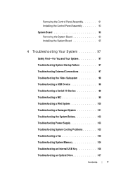
Contents 1 About Your System 11 Accessing System Features During Startup 11 Front-Panel Features and Indicators 12 Back-Panel Features and Indicators 14 Guidelines for Connecting External Devices 15 NIC Indicator Codes 16 Diagnostic Lights 17 System Messages 19 Warning Messages 22 Diagnostics Messages 22 Alert Messages 22 Other Information You May Need 23 2 Using the System Setup Program and Boot Manager 25 Choosing the System Boot Mode 25 Entering the System Setup Program 26 Responding to Error Messages 26 System Setup Options 27 Contents 3
Contents 1 About Your System 11 Accessing System Features During Startup 11 Front-Panel Features and Indicators 12 Back-Panel Features and Indicators 14 Guidelines for Connecting External Devices 15 NIC Indicator Codes 16 Diagnostic Lights 17 System Messages 19 Warning Messages 22 Diagnostics Messages 22 Alert Messages 22 Other Information You May Need 23 2 Using the System Setup Program and Boot Manager 25 Choosing the System Boot Mode 25 Entering the System Setup Program 26 Responding to Error Messages 26 System Setup Options 27 Contents 3
Owner's Manual
Page 7
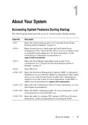
... System 97 Troubleshooting System Startup Failure 97 Troubleshooting External Connections 97 Troubleshooting the Video Subsystem 98 Troubleshooting a USB Device 98 Troubleshooting a Serial I/O Device 99 Troubleshooting a NIC 99 Troubleshooting a Wet System 100 Troubleshooting a Damaged System 101 Troubleshooting the System Battery 102 Troubleshooting Power Supply 103 Troubleshooting System Cooling Problems 103 Troubleshooting a Fan...
... System 97 Troubleshooting System Startup Failure 97 Troubleshooting External Connections 97 Troubleshooting the Video Subsystem 98 Troubleshooting a USB Device 98 Troubleshooting a Serial I/O Device 99 Troubleshooting a NIC 99 Troubleshooting a Wet System 100 Troubleshooting a Damaged System 101 Troubleshooting the System Battery 102 Troubleshooting Power Supply 103 Troubleshooting System Cooling Problems 103 Troubleshooting a Fan...
Owner's Manual
Page 11
...For more information, see the BMC or iDRAC user documentation at support.dell.com/manuals. Enters the utility to system features during startup. For more information, see the documentation for your integrated NIC. Enters the SAS Configuration Utility. For more information, see the documentation..." on the system's boot configuration. 1 About Your System Accessing System Features During Startup The following keystrokes provide access to configure NIC settings for PXE boot. Starts PXE boot. See "Using the System Setup Program and Boot Manager" on page 25. Enters ...
...For more information, see the BMC or iDRAC user documentation at support.dell.com/manuals. Enters the utility to system features during startup. For more information, see the documentation for your integrated NIC. Enters the SAS Configuration Utility. For more information, see the documentation..." on the system's boot configuration. 1 About Your System Accessing System Features During Startup The following keystrokes provide access to configure NIC settings for PXE boot. Starts PXE boot. See "Using the System Setup Program and Boot Manager" on page 25. Enters ...
Owner's Manual
Page 13
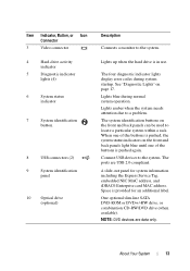
... one of the buttons is in use. Connect USB devices to the system. Space is provided for system information including the Express Service Tag, embedded NIC MAC address, and iDRAC6 Enterprise card MAC address. Item Indicator, Button, or Icon Connector 3 Video connector 4 Hard-drive activity indicator 5 Diagnostic indicator lights (4) 6 System status...
... one of the buttons is in use. Connect USB devices to the system. Space is provided for system information including the Express Service Tag, embedded NIC MAC address, and iDRAC6 Enterprise card MAC address. Item Indicator, Button, or Icon Connector 3 Video connector 4 Hard-drive activity indicator 5 Diagnostic indicator lights (4) 6 System status...

Owner's Manual
Page 14
... card slot 4 Serial connector 5 Video connector 6 eSATA 7 USB connectors (2) 8 Ethernet connectors (2) Description Dedicated management port for the optional iDRAC6 Enterprise card. Embedded 10/100/1000 NIC connectors. 14 About Your System Connects a PCI Express expansion card. Connects a VGA display to the system. Figure 1-2. Connects additional storage devices. Connects an external SD...
... card slot 4 Serial connector 5 Video connector 6 eSATA 7 USB connectors (2) 8 Ethernet connectors (2) Description Dedicated management port for the optional iDRAC6 Enterprise card. Embedded 10/100/1000 NIC connectors. 14 About Your System Connects a PCI Express expansion card. Connects a VGA display to the system. Figure 1-2. Connects additional storage devices. Connects an external SD...

Owner's Manual
Page 16
blinking 16 About Your System Link indicator is amber The NIC is connected to a valid network link at 10/100 Mbps. Activity indicator is green Network data is not connected to a valid network link at 1000 Mbps. Link indicator is green The NIC is connected to the network. NIC Indicator Codes 1 2 1 link indicator 2 activity indicator Indicator Indicator Code Link and activity indicators are off The NIC is being sent or received. NIC Indicator Codes Figure 1-3.
blinking 16 About Your System Link indicator is amber The NIC is connected to a valid network link at 10/100 Mbps. Activity indicator is green Network data is not connected to a valid network link at 1000 Mbps. Link indicator is green The NIC is connected to the network. NIC Indicator Codes 1 2 1 link indicator 2 activity indicator Indicator Indicator Code Link and activity indicators are off The NIC is being sent or received. NIC Indicator Codes Figure 1-3.
Owner's Manual
Page 32
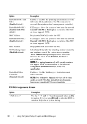
... is present. Displays the MAC address for a given device, or select Default to allow the BIOS to manually select an IRQ for the NIC. Sets a timer to boot from the network. When Disabled, the timer is disabled, remote access features such as virtual KVM are not available.... Option Embedded NIC1 and NIC2 (Enabled default) Embedded Gb NIC1 (Enabled with iSCSI Boot option is available if the NIC on board supports iSCSI. NOTE: This field can be accessed through the system's management controller). Enabled with PXE default) MAC Address Embedded Gb...
... is present. Displays the MAC address for a given device, or select Default to allow the BIOS to manually select an IRQ for the NIC. Sets a timer to boot from the network. When Disabled, the timer is disabled, remote access features such as virtual KVM are not available.... Option Embedded NIC1 and NIC2 (Enabled default) Embedded Gb NIC1 (Enabled with iSCSI Boot option is available if the NIC on board supports iSCSI. NOTE: This field can be accessed through the system's management controller). Enabled with PXE default) MAC Address Embedded Gb...
Owner's Manual
Page 44
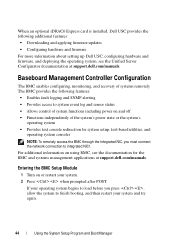
... additional features: • Downloading and applying firmware updates • Configuring hardware and firmware For more information about setting up Dell USC, configuring hardware and firmware, and deploying the operating system, see the documentation for system setup, text-based utilities, ...and operating system consoles NOTE: To remotely access the BMC through the integrated NIC, you press , allow the system to integrated NIC1. Baseboard Management Controller Configuration The BMC enables configuring, monitoring, and recovery...
... additional features: • Downloading and applying firmware updates • Configuring hardware and firmware For more information about setting up Dell USC, configuring hardware and firmware, and deploying the operating system, see the documentation for system setup, text-based utilities, ...and operating system consoles NOTE: To remotely access the BMC through the integrated NIC, you press , allow the system to integrated NIC1. Baseboard Management Controller Configuration The BMC enables configuring, monitoring, and recovery...
Owner's Manual
Page 99
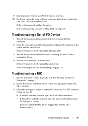
...device. See "Running the System Diagnostics" on page 111. 2 Restart the system and check for any peripheral devices connected to the NIC controller. 3 Check the appropriate indicator on the system and the serial device. Remove and reinstall the drivers if applicable. If the problem... persists, replace the device. Troubleshooting a NIC 1 Run the appropriate online diagnostic test. See the NIC's documentation. See "NIC Indicator Codes" on each USB device one at a time. 10 If a device causes the same problem...
...device. See "Running the System Diagnostics" on page 111. 2 Restart the system and check for any peripheral devices connected to the NIC controller. 3 Check the appropriate indicator on the system and the serial device. Remove and reinstall the drivers if applicable. If the problem... persists, replace the device. Troubleshooting a NIC 1 Run the appropriate online diagnostic test. See the NIC's documentation. See "NIC Indicator Codes" on each USB device one at a time. 10 If a device causes the same problem...
Owner's Manual
Page 100
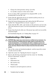
... NIC, see "Getting Help" on the network are enabled. See the NIC's documentation. 5 Enter the System Setup program and confirm that the NICs... on the switch or hub. If you are using a NIC card instead of the proper type and do not exceed the... drives • USB memory key • NIC hardware key • VFlash media • Expansion card and expansion-card... 100 Troubleshooting Your System See the documentation for the NIC card. 4 Ensure that came with the product. ...the System" on page 31. 6 Ensure that the NIC ports are all set to servicing that all troubleshooting fails, see...
... NIC, see "Getting Help" on the network are enabled. See the NIC's documentation. 5 Enter the System Setup program and confirm that the NICs... on the switch or hub. If you are using a NIC card instead of the proper type and do not exceed the... drives • USB memory key • NIC hardware key • VFlash media • Expansion card and expansion-card... 100 Troubleshooting Your System See the documentation for the NIC card. 4 Ensure that came with the product. ...the System" on page 31. 6 Ensure that the NIC ports are all set to servicing that all troubleshooting fails, see...
Owner's Manual
Page 111
... Features The system diagnostics provides a series of the diagnostics is reached • View help you are available at support.dell.com and on the media that include diagnostic tests on chassis and storage components such as hard drives, physical memory, communications and... printer ports, NICs, CMOS, and more. The files required to identify the problem using diagnostics, see the Dell Online Diagnostics User's Guide. Online Diagnostics is a suite of tests • Repeat tests •...
... Features The system diagnostics provides a series of the diagnostics is reached • View help you are available at support.dell.com and on the media that include diagnostic tests on chassis and storage components such as hard drives, physical memory, communications and... printer ports, NICs, CMOS, and more. The files required to identify the problem using diagnostics, see the Dell Online Diagnostics User's Guide. Online Diagnostics is a suite of tests • Repeat tests •...
Owner's Manual
Page 122
..., 108 hard drives (cabled) removing, 56 heat sink, 84 I iDRAC Configuration Utility, 45 iDRAC6 Enterprise Card, 79 iDRAC6 Express Card, 76 indicators back-panel, 14 NIC, 16 installing control panel assembly, 93 cooling shroud, 69 expansion card, 62 K keyboards troubleshooting, 98 M memory troubleshooting, 104 memory modules (DIMMs) configuring, 69 installing, 71...
..., 108 hard drives (cabled) removing, 56 heat sink, 84 I iDRAC Configuration Utility, 45 iDRAC6 Enterprise Card, 79 iDRAC6 Express Card, 76 indicators back-panel, 14 NIC, 16 installing control panel assembly, 93 cooling shroud, 69 expansion card, 62 K keyboards troubleshooting, 98 M memory troubleshooting, 104 memory modules (DIMMs) configuring, 69 installing, 71...
Owner's Manual
Page 124
... drive, 107 cooling fan, 103 damaged system, 101 expansion card, 109 external connections, 97 hard drive, 108 internal USB key, 106 keyboard, 98 memory, 104 NIC, 99 power supply, 103 processor, 110 system cooling, 103 video, 98 wet system, 100 U UEFI Boot Manager entering, 37 main screen, 38 System Utilities screen...
... drive, 107 cooling fan, 103 damaged system, 101 expansion card, 109 external connections, 97 hard drive, 108 internal USB key, 106 keyboard, 98 memory, 104 NIC, 99 power supply, 103 processor, 110 system cooling, 103 video, 98 wet system, 100 U UEFI Boot Manager entering, 37 main screen, 38 System Utilities screen...


