User Manual
Page 1
Dell PowerEdge R210 II Systems- Information Update Dell Systems Build and Update Utility The following operating systems are displayed but not supported by the Systems Service and Diagnostic Tools: • Red Hat Enterprise Linux 5.5(x32) • Red Hat Enterprise Linux 5.5(x64) • SUSE Linux Enterprise Server 10 SP3 (x64) March 2011 Dell Systems Service and Diagnostic Tools The following drivers are displayed but not supported by the Systems Build Update Utility (SBUU): • Red Hat Enterprise...
Dell PowerEdge R210 II Systems- Information Update Dell Systems Build and Update Utility The following operating systems are displayed but not supported by the Systems Service and Diagnostic Tools: • Red Hat Enterprise Linux 5.5(x32) • Red Hat Enterprise Linux 5.5(x64) • SUSE Linux Enterprise Server 10 SP3 (x64) March 2011 Dell Systems Service and Diagnostic Tools The following drivers are displayed but not supported by the Systems Build Update Utility (SBUU): • Red Hat Enterprise...
User Manual
Page 9
Dell PowerEdge R210 II Dell Systems Build and Update Utility 以下の OS Systems Build Update Utility(SBUU Red Hat Enterprise Linux 5.5(x32) • Red Hat Enterprise Linux 5.5(x64) • SUSE Linux Enterprise Server 10 SP3(x64) • VMware ESX 4.0 Update 3 • VMware ESXi 4.0 Update 3 Installable SBUU Microsoft Windows Server 2008 R2(x64 OS 用の Broadcom Ethernet Microsoft Windows Small...
Dell PowerEdge R210 II Dell Systems Build and Update Utility 以下の OS Systems Build Update Utility(SBUU Red Hat Enterprise Linux 5.5(x32) • Red Hat Enterprise Linux 5.5(x64) • SUSE Linux Enterprise Server 10 SP3(x64) • VMware ESX 4.0 Update 3 • VMware ESXi 4.0 Update 3 Installable SBUU Microsoft Windows Server 2008 R2(x64 OS 用の Broadcom Ethernet Microsoft Windows Small...
Owner's Manual
Page 21
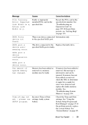
... problem persists, replace the system battery. SATA Portx device not found. Memory has been added or removed or a memory module may be ignored. See "System Battery" on page 119. Faulty or improperly installed PCIe card in the specified slot number. See "Troubleshooting an Expansion Card" on page 109. Time-of system memory has changed. If memory has not been added or removed, check the SEL to the specified SATA port. The drive connected to the Replace the faulty drive. Message...
... problem persists, replace the system battery. SATA Portx device not found. Memory has been added or removed or a memory module may be ignored. See "System Battery" on page 119. Faulty or improperly installed PCIe card in the specified slot number. See "Troubleshooting an Expansion Card" on page 109. Time-of system memory has changed. If memory has not been added or removed, check the SEL to the specified SATA port. The drive connected to the Replace the faulty drive. Message...
Owner's Manual
Page 25
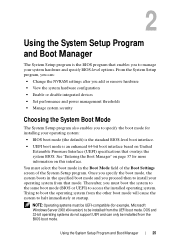
... boot mode (BIOS or UEFI) to specify the boot mode for more information on Unified Extensible Firmware Interface (UEFI) specifications that enables you to access the installed operating system. Trying to boot the operating system from the BIOS boot mode. Using the System Setup Program and Boot Manager 25 DOS and 32-bit operating systems do not support UEFI and can : • Change the NVRAM settings after you add or remove hardware • View the system hardware configuration • Enable or disable integrated devices • Set performance and power management thresholds...
... boot mode (BIOS or UEFI) to specify the boot mode for more information on Unified Extensible Firmware Interface (UEFI) specifications that enables you to access the installed operating system. Trying to boot the operating system from the BIOS boot mode. Using the System Setup Program and Boot Manager 25 DOS and 32-bit operating systems do not support UEFI and can : • Change the NVRAM settings after you add or remove hardware • View the system hardware configuration • Enable or disable integrated devices • Set performance and power management thresholds...
Owner's Manual
Page 28
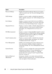
... settings. Displays a screen to specify related features and options. See "Serial Communication Screen" on page 31. See "Integrated Devices Screen" on page 33. Displays a screen to the processor (speed, cache size, and so on the PCI bus, and any installed expansion card that requires an IRQ. Option Processor Settings SATA Settings Boot Settings Integrated Devices PCI IRQ Assignment Serial Communication Power Management System Security Keyboard NumLock (On default) Description Displays information related to enable or disable the integrated SATA controller...
... settings. Displays a screen to specify related features and options. See "Serial Communication Screen" on page 31. See "Integrated Devices Screen" on page 33. Displays a screen to the processor (speed, cache size, and so on the PCI bus, and any installed expansion card that requires an IRQ. Option Processor Settings SATA Settings Boot Settings Integrated Devices PCI IRQ Assignment Serial Communication Power Management System Security Keyboard NumLock (On default) Description Displays information related to enable or disable the integrated SATA controller...
Owner's Manual
Page 30
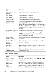
... SATA (AHCI default) Port A (Auto default) Port B (Off default) Description Allows the embedded SATA to Enabled, the processor can operate in the processor. Auto enables BIOS support for the device attached to SATA port B. If set to be running virtualization software. If Turbo Boost technology is supported by the processor, Turbo Mode is monitored by the BIOS. Enables or disables Execute Disable Memory Protection Technology. When set to Off, ATA, AHCI, or RAID modes. Displays the number of cores of Cores per Processor (All default) Turbo Mode (Enabled default...
... SATA (AHCI default) Port A (Auto default) Port B (Off default) Description Allows the embedded SATA to Enabled, the processor can operate in the processor. Auto enables BIOS support for the device attached to SATA port B. If set to be running virtualization software. If Turbo Boost technology is supported by the processor, Turbo Mode is monitored by the BIOS. Enables or disables Execute Disable Memory Protection Technology. When set to Off, ATA, AHCI, or RAID modes. Displays the number of cores of Cores per Processor (All default) Turbo Mode (Enabled default...
Owner's Manual
Page 31
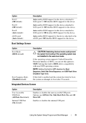
...All Ports Off. Enables or disables the internal USB port. Auto enables BIOS support for the device. Auto enables BIOS support for the device. If the operating system supports Unified Extensible Firmware Interface (UEFI), you can set this field to the eSATA port. Off disables BIOS support for the device attached to UEFI disables the Boot Sequence, Hard-Disk Drive Sequence, and USB Flash Drive Emulation Type fields. Off disables BIOS support for the device attached to SATA port C. Auto enables BIOS support for the device. Using the System Setup Program and Boot Manager...
...All Ports Off. Enables or disables the internal USB port. Auto enables BIOS support for the device. Auto enables BIOS support for the device. If the operating system supports Unified Extensible Firmware Interface (UEFI), you can set this field to the eSATA port. Off disables BIOS support for the device attached to UEFI disables the Boot Sequence, Hard-Disk Drive Sequence, and USB Flash Drive Emulation Type fields. Off disables BIOS support for the device attached to SATA port C. Auto enables BIOS support for the device. Using the System Setup Program and Boot Manager...
Owner's Manual
Page 36
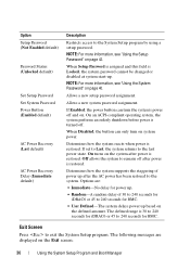
... Disabled, the button can turn on page 40. The following messages are : • Immediate-No delay for power up. • Random-A random delay of power up . Option Setup Password (Not Enabled default) Password Status (Unlocked default) Set Setup Password Set System Password Power Button (Enabled default) AC Power Recovery (Last default) AC Power Recovery Delay (Immediate default) Description Restricts access to the System Setup program by using a setup password. NOTE: For more information, see "Using the System Password" on system power. NOTE: For more information, see "Using...
... Disabled, the button can turn on page 40. The following messages are : • Immediate-No delay for power up. • Random-A random delay of power up . Option Setup Password (Not Enabled default) Password Status (Unlocked default) Set Setup Password Set System Password Power Button (Enabled default) AC Power Recovery (Last default) AC Power Recovery Delay (Immediate default) Description Restricts access to the System Setup program by using a setup password. NOTE: For more information, see "Using the System Password" on system power. NOTE: For more information, see "Using...
Owner's Manual
Page 43
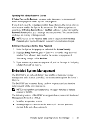
... and Boot Manager 43 NOTE: You can use the Password Status option in three attempts, the system lets you want to clear the existing setup password. NOTE: Certain platform configurations may not support the full set of the operating system. Press twice to assign a new setup password, perform the steps in "Assigning a Setup Password" on systems with the Setup Password option to access the setup password window. The setting changes to Not Enabled. 3 If you view...
... and Boot Manager 43 NOTE: You can use the Password Status option in three attempts, the system lets you want to clear the existing setup password. NOTE: Certain platform configurations may not support the full set of the operating system. Press twice to assign a new setup password, perform the steps in "Assigning a Setup Password" on systems with the Setup Password option to access the setup password window. The setting changes to Not Enabled. 3 If you view...
Owner's Manual
Page 44
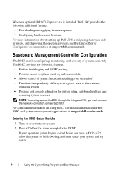
... again. 44 Using the System Setup Program and Boot Manager When an optional iDRAC6 Express card is installed, Dell USC provides the following features: • Enables fault logging and SNMP alerting • Provides access to system event log and sensor status • Allows control of system functions including power on using BMC, see the Unified Server Configurator documentation at support.dell.com/manuals. If your operating system begins to load before you must connect the network connection to integrated...
... again. 44 Using the System Setup Program and Boot Manager When an optional iDRAC6 Express card is installed, Dell USC provides the following features: • Enables fault logging and SNMP alerting • Provides access to system event log and sensor status • Allows control of system functions including power on using BMC, see the Unified Server Configurator documentation at support.dell.com/manuals. If your operating system begins to load before you must connect the network connection to integrated...
Owner's Manual
Page 58
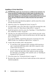
.... 1 Turn off the system and attached peripherals, and disconnect the system from the electrical outlet. 2 Open the system. Installing a 3.5-Inch Hard Drive CAUTION: Many repairs may only be done by the online or telephone service and support team. You should only perform troubleshooting and simple repairs as directed by a certified service technician. See Figure 6-1. • If connecting to a SAS RAID controller card (SAS or SATA hard drives), connect the data cable to the SATA connector...
.... 1 Turn off the system and attached peripherals, and disconnect the system from the electrical outlet. 2 Open the system. Installing a 3.5-Inch Hard Drive CAUTION: Many repairs may only be done by the online or telephone service and support team. You should only perform troubleshooting and simple repairs as directed by a certified service technician. See Figure 6-1. • If connecting to a SAS RAID controller card (SAS or SATA hard drives), connect the data cable to the SATA connector...
Owner's Manual
Page 86
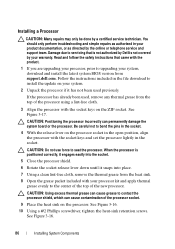
... to servicing that came with the product. 1 If you are upgrading your processor, prior to upgrading your system, download and install the latest system BIOS version from support.dell.com. See Figure 3-17. CAUTION: Using excess thermal grease can cause grease to the center of the top of the processor using a lint-free cloth. 3 Align the processor with the socket keys and set the processor lightly in the open...
... to servicing that came with the product. 1 If you are upgrading your processor, prior to upgrading your system, download and install the latest system BIOS version from support.dell.com. See Figure 3-17. CAUTION: Using excess thermal grease can cause grease to the center of the top of the processor using a lint-free cloth. 3 Align the processor with the socket keys and set the processor lightly in the open...
Owner's Manual
Page 91
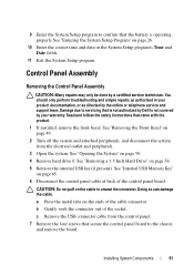
Damage due to the chassis and remove the board. a Press the metal tabs on the cable to confirm that the battery is not covered by your product documentation, or as directed by the online or telephone service and support team. See "Internal USB Memory Key" on page 65. 6 Disconnect the control panel cable at back of the control panel board: CAUTION: Do not pull on the ends of the socket...
Damage due to the chassis and remove the board. a Press the metal tabs on the cable to confirm that the battery is not covered by your product documentation, or as directed by the online or telephone service and support team. See "Internal USB Memory Key" on page 65. 6 Disconnect the control panel cable at back of the control panel board: CAUTION: Do not pull on the ends of the socket...
Owner's Manual
Page 99
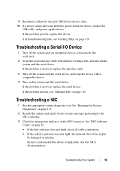
... diagnostic test. See "Running the System Diagnostics" on page 111. 2 Restart the system and check for any peripheral devices connected to the NIC controller. 3 Check the appropriate indicator on the system and the serial device. See "NIC Indicator Codes" on page 119. If the problem persists, replace the device. If the problem is resolved, replace the interface cable. 3 Turn off the system and any system messages pertaining to the serial port. 2 Swap the serial interface cable with a comparable device. 4 Turn...
... diagnostic test. See "Running the System Diagnostics" on page 111. 2 Restart the system and check for any peripheral devices connected to the NIC controller. 3 Check the appropriate indicator on the system and the serial device. See "NIC Indicator Codes" on page 119. If the problem persists, replace the device. If the problem is resolved, replace the interface cable. 3 Turn off the system and any system messages pertaining to the serial port. 2 Swap the serial interface cable with a comparable device. 4 Turn...
Owner's Manual
Page 100
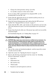
... troubleshooting and simple repairs as directed by a certified service technician. See "Installing System Components" on the network are enabled. If all set to servicing that the NICs, hubs, and switches on page 47. • Hard drives • USB memory key • NIC hardware key • VFlash media • Expansion card and expansion-card riser 100 Troubleshooting Your System See "Opening the System" on page 119. See the documentation for each network device. 7 Ensure that the NIC ports are all troubleshooting fails...
... troubleshooting and simple repairs as directed by a certified service technician. See "Installing System Components" on the network are enabled. If all set to servicing that the NICs, hubs, and switches on page 47. • Hard drives • USB memory key • NIC hardware key • VFlash media • Expansion card and expansion-card riser 100 Troubleshooting Your System See "Opening the System" on page 119. See the documentation for each network device. 7 Ensure that the NIC ports are all troubleshooting fails...
Owner's Manual
Page 107
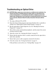
... page 26. 3 Run the appropriate online diagnostic test. See "Opening the System" on page 50. 6 Ensure that the interface cable is securely connected to the optical drive and to the controller. 7 Ensure that a power cable is not resolved, see "Getting Help" on page 51. If the problem is properly connected to servicing that the drive's controller is not covered by Dell is enabled. Troubleshooting an Optical Drive CAUTION: Many repairs may only...
... page 26. 3 Run the appropriate online diagnostic test. See "Opening the System" on page 50. 6 Ensure that the interface cable is securely connected to the optical drive and to the controller. 7 Ensure that a power cable is not resolved, see "Getting Help" on page 51. If the problem is properly connected to servicing that the drive's controller is not covered by Dell is enabled. Troubleshooting an Optical Drive CAUTION: Many repairs may only...

Owner's Manual
Page 108
... adapter configuration utility program by your warranty. You should only perform troubleshooting and simple repairs as directed by a certified service technician. d Exit the configuration utility and allow the system to boot to servicing that the drives appear in the System Setup program. See the operating system documentation for the RAID array. Troubleshooting a Hard Drive CAUTION: Many repairs may only be done by the online or telephone service and support team. See the documentation supplied...
... adapter configuration utility program by your warranty. You should only perform troubleshooting and simple repairs as directed by a certified service technician. d Exit the configuration utility and allow the system to boot to servicing that the drives appear in the System Setup program. See the operating system documentation for the RAID array. Troubleshooting a Hard Drive CAUTION: Many repairs may only be done by the online or telephone service and support team. See the documentation supplied...
Owner's Manual
Page 111
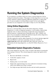
... a user-defined error limit is reached • View help you are available at support.dell.com and on chassis and storage components such as hard drives, physical memory, communications and printer ports, NICs, CMOS, and more. The system diagnostics menus and options allow you experience a problem with your system, run the online diagnostics for systems running supported Microsoft Windows and Linux operating systems are unable to identify the problem using diagnostics, see the Dell Online Diagnostics User's Guide. The files required...
... a user-defined error limit is reached • View help you are available at support.dell.com and on chassis and storage components such as hard drives, physical memory, communications and printer ports, NICs, CMOS, and more. The system diagnostics menus and options allow you experience a problem with your system, run the online diagnostics for systems running supported Microsoft Windows and Linux operating systems are unable to identify the problem using diagnostics, see the Dell Online Diagnostics User's Guide. The files required...
Owner's Manual
Page 123
...phone numbers, 119 POST accessing system features, 11 power supply removing, 87 replacing, 89 troubleshooting, 103 processor removing, 82, 86 See processor. See hard drive. SATA hard drive. startup accessing system features, 11 support contacting Dell, 119 system closing, 51 opening, 50 system board Index 123 See hard drive. securing your system, 35, 41 setup password, 42 slots See expansion slots. troubleshooting, 110 upgrades, 82 R removing bezel, 49 control panel assembly, 91 cooling shroud, 67 cover, 50 expansion card, 61 hard drive (cabled), 56 memory modules, 73 power supply...
...phone numbers, 119 POST accessing system features, 11 power supply removing, 87 replacing, 89 troubleshooting, 103 processor removing, 82, 86 See processor. See hard drive. SATA hard drive. startup accessing system features, 11 support contacting Dell, 119 system closing, 51 opening, 50 system board Index 123 See hard drive. securing your system, 35, 41 setup password, 42 slots See expansion slots. troubleshooting, 110 upgrades, 82 R removing bezel, 49 control panel assembly, 91 cooling shroud, 67 cover, 50 expansion card, 61 hard drive (cabled), 56 memory modules, 73 power supply...

Processor Information
Page 1
...'s Owner's Manual at support.dell.com. • Intel Xeon E3-1200 v2 series processors support: - Intel Xeon E3-1200 v2 Series Processors-Information Update Important Information • The Dell PowerEdge R210 II and T110 II systems, originally installed with Intel Xeon E3-1200 series processors, support Intel Xeon E3-1200 v2 series processors after a BIOS and baseboard management controller (BMC) firmware upgrade. • To support Intel Xeon E3-1200 v2 series processors on the memory configuration guidelines...
...'s Owner's Manual at support.dell.com. • Intel Xeon E3-1200 v2 series processors support: - Intel Xeon E3-1200 v2 Series Processors-Information Update Important Information • The Dell PowerEdge R210 II and T110 II systems, originally installed with Intel Xeon E3-1200 series processors, support Intel Xeon E3-1200 v2 series processors after a BIOS and baseboard management controller (BMC) firmware upgrade. • To support Intel Xeon E3-1200 v2 series processors on the memory configuration guidelines...


