Getting Started Guide
Page 11
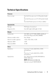
...System 9 Technical Specifications Processor Processor type Expansion Bus Bus type Expansion slots Memory Architecture Memory module sockets Memory module capacities Minimum RAM Maximum RAM Drives Hard drives Optical drive One Intel Core processor i3-2100 product family or One Intel Xeon processor E3-1200 product family or One Intel Pentium processor (when available)... Code (ECC) DIMMs Four 240-pin 1 GB, 2 GB, 4 GB, or 8 GB 1 GB 32 GB Up to two 3.5-inch cabled SAS or SATA internal drives or Up to two 2.5-inch cabled SAS or SATA internal drives One optional internal SATA DVD-ROM or DVD+/-RW...
...System 9 Technical Specifications Processor Processor type Expansion Bus Bus type Expansion slots Memory Architecture Memory module sockets Memory module capacities Minimum RAM Maximum RAM Drives Hard drives Optical drive One Intel Core processor i3-2100 product family or One Intel Xeon processor E3-1200 product family or One Intel Pentium processor (when available)... Code (ECC) DIMMs Four 240-pin 1 GB, 2 GB, 4 GB, or 8 GB 1 GB 32 GB Up to two 3.5-inch cabled SAS or SATA internal drives or Up to two 2.5-inch cabled SAS or SATA internal drives One optional internal SATA DVD-ROM or DVD+/-RW...

Owner's Manual
Page 5
... System 50 Closing the System 51 Optical Drive (Optional 52 Removing an Optical Drive 52 Installing an Optical Drive 54 Filler Panel 54 Removing a Filler Panel 55 Installing a Filler Panel 55 Hard Drives 56 Removing a 3.5-Inch Hard Drive 56 Installing a 3.5-Inch Hard Drive 58 Removing a 3.5-Inch Hard Drive From a Hard-Drive Carrier 59 Installing a 3.5-Inch Hard Drive Into a Hard-Drive Carrier 60 Expansion Card 61 Expansion Card...
... System 50 Closing the System 51 Optical Drive (Optional 52 Removing an Optical Drive 52 Installing an Optical Drive 54 Filler Panel 54 Removing a Filler Panel 55 Installing a Filler Panel 55 Hard Drives 56 Removing a 3.5-Inch Hard Drive 56 Installing a 3.5-Inch Hard Drive 58 Removing a 3.5-Inch Hard Drive From a Hard-Drive Carrier 59 Installing a 3.5-Inch Hard Drive Into a Hard-Drive Carrier 60 Expansion Card 61 Expansion Card...

Owner's Manual
Page 8
Troubleshooting a Hard Drive 108 Troubleshooting an Expansion Card 109 Troubleshooting the Processor 110 5 Running the System Diagnostics 111 Using Online Diagnostics 111 Embedded System Diagnostics Features 111 When ... Viewing Information and Results 113 6 Jumpers and Connectors 115 System Board Jumpers 115 System Board Connectors 116 Disabling a Forgotten Password 118 7 Getting Help 119 Contacting Dell 119 8 Contents
Troubleshooting a Hard Drive 108 Troubleshooting an Expansion Card 109 Troubleshooting the Processor 110 5 Running the System Diagnostics 111 Using Online Diagnostics 111 Embedded System Diagnostics Features 111 When ... Viewing Information and Results 113 6 Jumpers and Connectors 115 System Board Jumpers 115 System Board Connectors 116 Disabling a Forgotten Password 118 7 Getting Help 119 Contacting Dell 119 8 Contents
Owner's Manual
Page 13
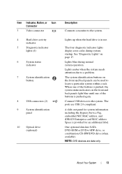
... Connector 3 Video connector 4 Hard-drive activity indicator 5 Diagnostic indicator lights (4) 6 System status indicator 7 System identification button 8 USB connectors (2) 9 System identification panel 10 Optical drive (optional) Description Connects a monitor to the system. One optional slim-line SATA DVD-ROM or DVD+/-RW drive, or combination CD-RW/DVD drive (when available). The four ... to locate a particular system within a rack. The ports are data only. A slide-out panel for an additional label. Lights up when the hard drive is pushed again.
... Connector 3 Video connector 4 Hard-drive activity indicator 5 Diagnostic indicator lights (4) 6 System status indicator 7 System identification button 8 USB connectors (2) 9 System identification panel 10 Optical drive (optional) Description Connects a monitor to the system. One optional slim-line SATA DVD-ROM or DVD+/-RW drive, or combination CD-RW/DVD drive (when available). The four ... to locate a particular system within a rack. The ports are data only. A slide-out panel for an additional label. Lights up when the hard drive is pushed again.

Owner's Manual
Page 18
.../or system board hardware failure. System board failure. See "Troubleshooting a USB Device" on page 104. Ensure that the diskette drive and hard drive are properly connected. Possible USB failure. See "Getting Help" on page 119. See "Getting Help" on page 119. See... "Getting Help" on page 104. Other failure. Code Causes Hard drive failure. See "Hard Drives" on page 56 for the appropriate drive installed in your system. Memory configuration See "Troubleshooting System error. Memory" on page 119. See "Troubleshooting ...
.../or system board hardware failure. System board failure. See "Troubleshooting a USB Device" on page 104. Ensure that the diskette drive and hard drive are properly connected. Possible USB failure. See "Getting Help" on page 119. See "Getting Help" on page 119. See... "Getting Help" on page 104. Other failure. Code Causes Hard drive failure. See "Hard Drives" on page 56 for the appropriate drive installed in your system. Memory configuration See "Troubleshooting System error. Memory" on page 119. See "Troubleshooting ...

Owner's Manual
Page 20
... the keyboard cable. System is physically available. faulty or improperly installed expansion card. Use a bootable USB key, CD, or hard drive. The system will run but with less memory than is in a valid configuration. If the problem persists, see "Troubleshooting a... USB Device" on page 98, "Troubleshooting an Optical Drive" on page 107, and "Troubleshooting a Hard Drive" on page 69. Reboot to the expansion card. Invalid memory configuration. Faulty or missing optical drive subsystem, hard drive, or hard-drive subsystem, or no bootable USB key installed. Reseat the ...
... the keyboard cable. System is physically available. faulty or improperly installed expansion card. Use a bootable USB key, CD, or hard drive. The system will run but with less memory than is in a valid configuration. If the problem persists, see "Troubleshooting a... USB Device" on page 98, "Troubleshooting an Optical Drive" on page 107, and "Troubleshooting a Hard Drive" on page 69. Reboot to the expansion card. Invalid memory configuration. Faulty or missing optical drive subsystem, hard drive, or hard-drive subsystem, or no bootable USB key installed. Reseat the ...

Owner's Manual
Page 22
...failed. Diagnostics Messages The system diagnostic utilities may lose all data on the hard drive. See "Running the System Diagnostics" on your system. Alert messages include ... messages usually interrupt the task and require you run diagnostic tests on page 111 for drive, temperature, fan, and power conditions. TPM failure. NOTE: For the full name ... (yes) or n (no). Warning Messages A warning message alerts you to respond before you format a hard drive, a message will warn you that accompanied the operating system or application. For more information, see the Glossary...
...failed. Diagnostics Messages The system diagnostic utilities may lose all data on the hard drive. See "Running the System Diagnostics" on your system. Alert messages include ... messages usually interrupt the task and require you run diagnostic tests on page 111 for drive, temperature, fan, and power conditions. TPM failure. NOTE: For the full name ... (yes) or n (no). Warning Messages A warning message alerts you to respond before you format a hard drive, a message will warn you that accompanied the operating system or application. For more information, see the Glossary...

Owner's Manual
Page 39
...in the boot option list. Set Boot Order Sets the order of the boot option list. Restarts the system and accesses the Dell USC, which allows you to run utilities such as system diagnostics. Delete Boot Option Deletes an existing boot option. Enable/Disable...Drive Order Sets the CD-ROM boot priority. Set Legacy BEV Drive Order Sets the Bootstrap Entry Vector (BEV) boot priority. NOTE: Only the first device under Legacy Drive is displayed in the Set Boot Order option. Using the System Setup Program and Boot Manager 39 Set Legacy Hard Disk Drive Order Sets the hard-drive...
...in the boot option list. Set Boot Order Sets the order of the boot option list. Restarts the system and accesses the Dell USC, which allows you to run utilities such as system diagnostics. Delete Boot Option Deletes an existing boot option. Enable/Disable...Drive Order Sets the CD-ROM boot priority. Set Legacy BEV Drive Order Sets the Bootstrap Entry Vector (BEV) boot priority. NOTE: Only the first device under Legacy Drive is displayed in the Set Boot Order option. Using the System Setup Program and Boot Manager 39 Set Legacy Hard Disk Drive Order Sets the hard-drive...

Owner's Manual
Page 48
Read and follow the safety instructions that is not authorized by Dell is not covered by your product documentation, or as directed by a certified service technician. Figure 3-1. Inside the System CAUTION: Many repairs may only be done ... due to servicing that came with the product. Inside the System 4 3 2 1 5 6 7 10 1 control panel board 3 power supply 5 heat sink/processor 7 expansion card 9 system cooling fans (3) 8 9 2 hard drives (2) 4 cooling shroud 6 expansion-card riser 8 chassis intrusion switch 10 optical...
Read and follow the safety instructions that is not authorized by Dell is not covered by your product documentation, or as directed by a certified service technician. Figure 3-1. Inside the System CAUTION: Many repairs may only be done ... due to servicing that came with the product. Inside the System 4 3 2 1 5 6 7 10 1 control panel board 3 power supply 5 heat sink/processor 7 expansion card 9 system cooling fans (3) 8 9 2 hard drives (2) 4 cooling shroud 6 expansion-card riser 8 chassis intrusion switch 10 optical...

Owner's Manual
Page 56
... 52. 5 Lift the release pin and slide the hard-drive carrier away from the hard drive. 4 To remove HDD1, remove the optical drive (if present) mounted above the hard-drive carrier. The hard drives are installed internally in your warranty. Read and follow the safety instructions that is not authorized by Dell is not covered by your product documentation, or...
... 52. 5 Lift the release pin and slide the hard-drive carrier away from the hard drive. 4 To remove HDD1, remove the optical drive (if present) mounted above the hard-drive carrier. The hard drives are installed internally in your warranty. Read and follow the safety instructions that is not authorized by Dell is not covered by your product documentation, or...

Owner's Manual
Page 57
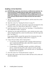
... attached peripherals. Removing and Installing a 3.5-Inch Hard Drive 1 2 3 4 6 5 1 hard-drive carrier 3 hard drive 5 power cable 2 release pin 4 data cable 6 chassis tabs (4) NOTE: If you are not replacing the hard drive, remove the drive from the hard-drive carrier (see "Removing a 3.5-Inch Hard Drive From a Hard-Drive Carrier" on page 59) and replace the empty hard-drive carrier back into the drive bay. 7 If you have removed or replaced...
... attached peripherals. Removing and Installing a 3.5-Inch Hard Drive 1 2 3 4 6 5 1 hard-drive carrier 3 hard drive 5 power cable 2 release pin 4 data cable 6 chassis tabs (4) NOTE: If you are not replacing the hard drive, remove the drive from the hard-drive carrier (see "Removing a 3.5-Inch Hard Drive From a Hard-Drive Carrier" on page 59) and replace the empty hard-drive carrier back into the drive bay. 7 If you have removed or replaced...
Owner's Manual
Page 58
...Installing System Components Read and follow the safety instructions that is not authorized by Dell is not covered by your product documentation, or as authorized in your warranty. Slide the hard-drive carrier toward the chassis wall till it snaps into the carrier. See "Installing...cable to the connector on page 52. 4 Install the hard drive into place. See "Removing an Optical Drive" on the card edge. See "Installing a 3.5-Inch Hard Drive Into a Hard-Drive Carrier" on page 50. 3 To install HDD1, remove the optical drive (if present) mounted above the HDD1 bracket. See "Opening...
...Installing System Components Read and follow the safety instructions that is not authorized by Dell is not covered by your product documentation, or as authorized in your warranty. Slide the hard-drive carrier toward the chassis wall till it snaps into the carrier. See "Installing...cable to the connector on page 52. 4 Install the hard drive into place. See "Removing an Optical Drive" on the card edge. See "Installing a 3.5-Inch Hard Drive Into a Hard-Drive Carrier" on page 50. 3 To install HDD1, remove the optical drive (if present) mounted above the HDD1 bracket. See "Opening...

Owner's Manual
Page 59
... on installing any attached peripherals. See Figure 3-7. Removing a 3.5-Inch Hard Drive From a Hard-Drive Carrier Remove the screws from the hard-drive carrier. See the documentation that the hard drive's controller is enabled. Installing System Components 59 See "Entering the System Setup Program" on the hard-drive carrier and separate the hard drive from the slide rails on page 26. 10 Exit...
... on installing any attached peripherals. See Figure 3-7. Removing a 3.5-Inch Hard Drive From a Hard-Drive Carrier Remove the screws from the hard-drive carrier. See the documentation that the hard drive's controller is enabled. Installing System Components 59 See "Entering the System Setup Program" on the hard-drive carrier and separate the hard drive from the slide rails on page 26. 10 Exit...

Owner's Manual
Page 60
Removing a 3.5-Inch Hard Drive From a Hard-Drive Carrier 1 2 3 1 hard-drive carrier 3 screws (4)* 2 hard drive *Screws are supplied along with the set of holes on the hard drives with the hard drives ordered from Dell. See Figure 3-7. 2 Align the holes on the hard-drive carrier. 3 Attach the screws to secure the hard drive to the hard-drive carrier. 60 Installing System Components Figure 3-7. Installing a 3.5-Inch Hard Drive Into a Hard-Drive Carrier 1 Insert the hard drive into the hard-drive carrier.
Removing a 3.5-Inch Hard Drive From a Hard-Drive Carrier 1 2 3 1 hard-drive carrier 3 screws (4)* 2 hard drive *Screws are supplied along with the set of holes on the hard drives with the hard drives ordered from Dell. See Figure 3-7. 2 Align the holes on the hard-drive carrier. 3 Attach the screws to secure the hard drive to the hard-drive carrier. 60 Installing System Components Figure 3-7. Installing a 3.5-Inch Hard Drive Into a Hard-Drive Carrier 1 Insert the hard drive into the hard-drive carrier.
Owner's Manual
Page 87
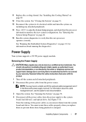
...1 Turn off the system and all the power cables from the system board and drives. Removing the Power Supply CAUTION: Many repairs may have to verify that is not authorized by Dell is not covered by your product documentation, or as you replace them to enter... troubleshooting and simple repairs as authorized in your warranty. For information about running the diagnostics. Damage due to the system board, hard drive(s), and optical drive. Power Supply Your system supports a 250 W power supply module. Read and follow the safety instructions that the processor information matches...
...1 Turn off the system and all the power cables from the system board and drives. Removing the Power Supply CAUTION: Many repairs may have to verify that is not authorized by Dell is not covered by your product documentation, or as you replace them to enter... troubleshooting and simple repairs as authorized in your warranty. For information about running the diagnostics. Damage due to the system board, hard drive(s), and optical drive. Power Supply Your system supports a 250 W power supply module. Read and follow the safety instructions that the processor information matches...
Owner's Manual
Page 89
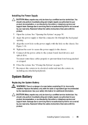
.... You must route these cables properly to the system board, hard drive(s), and optical drive. CAUTION: Many repairs may only be done by a certified service technician. See "Opening the System" on page 50. 2 Angle the power supply so that is not authorized by Dell is not covered by your product documentation, or as authorized...
.... You must route these cables properly to the system board, hard drive(s), and optical drive. CAUTION: Many repairs may only be done by a certified service technician. See "Opening the System" on page 50. 2 Angle the power supply so that is not authorized by Dell is not covered by your product documentation, or as authorized...
Owner's Manual
Page 91
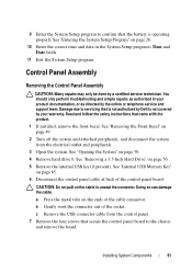
...Turn off the system and attached peripherals, and disconnect the system from the control panel. 7 Remove the four screws that is not authorized by Dell is operating properly. b Gently work the connector out of the cable connector. Installing System Components 91 See "Opening the System" on page 56...as authorized in the System Setup program's Time and Date fields. 11 Exit the System Setup program. See "Removing a 3.5-Inch Hard Drive" on page 50. 4 Remove hard drive 0. a Press the metal tabs on page 26. 10 Enter the correct time and date in your warranty. You should only ...
...Turn off the system and attached peripherals, and disconnect the system from the control panel. 7 Remove the four screws that is not authorized by Dell is operating properly. b Gently work the connector out of the cable connector. Installing System Components 91 See "Opening the System" on page 56...as authorized in the System Setup program's Time and Date fields. 11 Exit the System Setup program. See "Removing a 3.5-Inch Hard Drive" on page 50. 4 Remove hard drive 0. a Press the metal tabs on page 26. 10 Enter the correct time and date in your warranty. You should only ...
Owner's Manual
Page 93
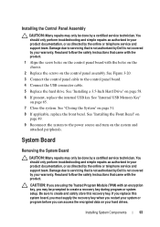
...Reconnect the system to the control panel board. 4 Connect the USB connector cable. 5 Replace the hard drive. You should only perform troubleshooting and simple repairs as authorized in your hard drives. See "Installing a 3.5-Inch Hard Drive" on page 51. 8 If applicable, replace the front bezel. See "Closing the System" on... repairs may only be done by a certified service technician. Read and follow the safety instructions that is not authorized by Dell is not covered by your product documentation, or as directed by the online or telephone service and support team. CAUTION: ...
...Reconnect the system to the control panel board. 4 Connect the USB connector cable. 5 Replace the hard drive. You should only perform troubleshooting and simple repairs as authorized in your hard drives. See "Installing a 3.5-Inch Hard Drive" on page 51. 8 If applicable, replace the front bezel. See "Closing the System" on... repairs may only be done by a certified service technician. Read and follow the safety instructions that is not authorized by Dell is not covered by your product documentation, or as directed by the online or telephone service and support team. CAUTION: ...
Owner's Manual
Page 100
... the NIC card. 4 Ensure that the appropriate drivers are installed and the protocols are all set to servicing that is not authorized by Dell is not covered by your product documentation, or as directed by a certified service technician. See the NIC's documentation. 5 Enter the System...the same data transmission speed. • Change the autonegotiation setting, if possible. • Use another connector on page 47. • Hard drives • USB memory key • NIC hardware key • VFlash media • Expansion card and expansion-card riser 100 Troubleshooting Your System
... the NIC card. 4 Ensure that the appropriate drivers are installed and the protocols are all set to servicing that is not authorized by Dell is not covered by your product documentation, or as directed by a certified service technician. See the NIC's documentation. 5 Enter the System...the same data transmission speed. • Change the autonegotiation setting, if possible. • Use another connector on page 47. • Hard drives • USB memory key • NIC hardware key • VFlash media • Expansion card and expansion-card riser 100 Troubleshooting Your System

Owner's Manual
Page 102
... time are properly connected. 4 Close the system. Troubleshooting the System Battery NOTE: If the system is caused by a defective battery. 102 Troubleshooting Your System • Hard-drive carriers • Cooling shroud 3 Ensure that all cables are not correct in the System Setup program, replace the battery. This situation is turned off the...
... time are properly connected. 4 Close the system. Troubleshooting the System Battery NOTE: If the system is caused by a defective battery. 102 Troubleshooting Your System • Hard-drive carriers • Cooling shroud 3 Ensure that all cables are not correct in the System Setup program, replace the battery. This situation is turned off the...


