Information Update - Processor Installation
Page 3
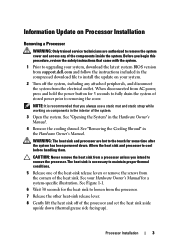
... outlet. WARNING: The heat sink and processor are authorized to remove the system cover and access any attached peripherals, and disconnect the system from AC power, press and hold the power button for 3 seconds to fully drain the system of the processor and set the heat sink aside upside down . Allow the heat sink and processor to remove the processor. Processor Installation 3 Information Update on your Hardware Owner's Manual for a system-specific illustration.
... outlet. WARNING: The heat sink and processor are authorized to remove the system cover and access any attached peripherals, and disconnect the system from AC power, press and hold the power button for 3 seconds to fully drain the system of the processor and set the heat sink aside upside down . Allow the heat sink and processor to remove the processor. Processor Installation 3 Information Update on your Hardware Owner's Manual for a system-specific illustration.

Dell PowerEdge M1000e Configuration Guide
Page 52
... /O module network settings for Ethernet passthrough or Infiniband switches. 1 Log in to configure the switch's out-of-band Ethernet port. NOTE: Do not attempt to configure I /O module configuration page, you must be different, and on page 52). The switch's in which the module is not saved to the I /O module's default IP address (if supported). Switch Modules Configuring a Switch Module Network Ethernet Port Using the Web-Based Interface You can configure your I/O switch modules using serial console redirection. • Direct access to the I/O module's serial port (if supported...
... /O module network settings for Ethernet passthrough or Infiniband switches. 1 Log in to configure the switch's out-of-band Ethernet port. NOTE: Do not attempt to configure I /O module configuration page, you must be different, and on page 52). The switch's in which the module is not saved to the I /O module's default IP address (if supported). Switch Modules Configuring a Switch Module Network Ethernet Port Using the Web-Based Interface You can configure your I/O switch modules using serial console redirection. • Direct access to the I/O module's serial port (if supported...
Hardware Owner's Manual
Page 119
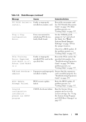
... the PCIe card in the specified slot number. Retry the BIOS update. Table 1-26. If the problem persists, see "Getting Help" on page 198. Run the System Setup program and review the current settings. BIOS Update Attempt Failed. Set the NVRAM_CLR jumper to install. Reseat the mezzanine card. See "Troubleshooting Expansion Cards" on " and reboot the blade. See "Troubleshooting Expansion Cards" on page 127. See "Using the System Setup Program and UEFI Boot Manager" on page 299. ROM bad checksum = address Expansion card improperly...
... the PCIe card in the specified slot number. Retry the BIOS update. Table 1-26. If the problem persists, see "Getting Help" on page 198. Run the System Setup program and review the current settings. BIOS Update Attempt Failed. Set the NVRAM_CLR jumper to install. Reseat the mezzanine card. See "Troubleshooting Expansion Cards" on " and reboot the blade. See "Troubleshooting Expansion Cards" on page 127. See "Using the System Setup Program and UEFI Boot Manager" on page 299. ROM bad checksum = address Expansion card improperly...
Hardware Owner's Manual
Page 127
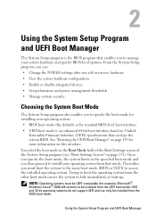
... UEFI Boot Manager" on page 139 for installing your system hardware and specify BIOS-level options. Thereafter, you to manage your operating system: • BIOS boot mode (the default) is the standard BIOS-level boot interface. • UEFI boot mode is the BIOS program that mode. DOS and 32-bit operating systems do not support UEFI and can : • Change the NVRAM settings after you add or remove hardware • View the system hardware configuration • Enable or disable integrated devices • Set performance and power management thresholds • Manage...
... UEFI Boot Manager" on page 139 for installing your system hardware and specify BIOS-level options. Thereafter, you to manage your operating system: • BIOS boot mode (the default) is the standard BIOS-level boot interface. • UEFI boot mode is the BIOS program that mode. DOS and 32-bit operating systems do not support UEFI and can : • Change the NVRAM settings after you add or remove hardware • View the system hardware configuration • Enable or disable integrated devices • Set performance and power management thresholds • Manage...

Hardware Owner's Manual
Page 131
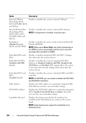
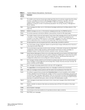
...run virtualization software. Displays when the processors support Virtualization Technology. This feature can also set to a higher value (1.5 V) provided that supports Virtualization Technology. Options are Mirror Mode, Spare Mode, and Disabled. NOTE: M710HD systems installed with Intel® Xeon® 5600 series processors support memory sparing. Node Interleaving (Disabled default) If set the voltage of the installed memory (Auto default) modules. Processor Settings Screen Option 64-bit Core Speed Bus Speed Logical Processor (Enabled default) Virtualization Technology (Disabled...
...run virtualization software. Displays when the processors support Virtualization Technology. This feature can also set to a higher value (1.5 V) provided that supports Virtualization Technology. Options are Mirror Mode, Spare Mode, and Disabled. NOTE: M710HD systems installed with Intel® Xeon® 5600 series processors support memory sparing. Node Interleaving (Disabled default) If set the voltage of the installed memory (Auto default) modules. Processor Settings Screen Option 64-bit Core Speed Bus Speed Logical Processor (Enabled default) Virtualization Technology (Disabled...
Hardware Owner's Manual
Page 134
... Mirror Mode, the vFlash functionality of an additional driver. 134 Using the System Setup Program and UEFI Boot Manager This field does not have user-selectable settings. iSCSI MAC Address Displays the iSCSI MAC address for Internal Dual SD Module (IDSDM). NOTE: When set to boot from the network. Changes take effect after the system reboots. MAC Address Displays the MAC address for a particular integrated NIC. Capability Detected Displays the features provided by the hardware key installed in...
... Mirror Mode, the vFlash functionality of an additional driver. 134 Using the System Setup Program and UEFI Boot Manager This field does not have user-selectable settings. iSCSI MAC Address Displays the iSCSI MAC address for Internal Dual SD Module (IDSDM). NOTE: When set to boot from the network. Changes take effect after the system reboots. MAC Address Displays the MAC address for a particular integrated NIC. Capability Detected Displays the features provided by the hardware key installed in...
Hardware Owner's Manual
Page 290
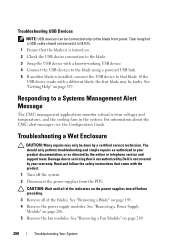
... or telephone service and support team. Read and follow the safety instructions that the blade(s) is turned on the power supplies turn off the system. 2 Disconnect the power supplies from the PDU. CAUTION: Wait until all of a USB cable should only perform troubleshooting and simple repairs as directed by your product documentation, or as authorized in the system. See "Removing a Fan Module" on page 266. 5 Remove the fan modules. Damage...
... or telephone service and support team. Read and follow the safety instructions that the blade(s) is turned on the power supplies turn off the system. 2 Disconnect the power supplies from the PDU. CAUTION: Wait until all of a USB cable should only perform troubleshooting and simple repairs as directed by your product documentation, or as authorized in the system. See "Removing a Fan Module" on page 266. 5 Remove the fan modules. Damage...
Web Tools Administrator’s Guide
Page 168
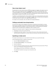
... name. Use the following tasks: • Specifying a remote server to store the files. • Enabling the automatic transfer of trace dumps to the system error log. Enter the FTP host IP address, path of the remote directory for the trace dump files, FTP user name, and FTP password in as part of standard switch configuration, before you can also generate a trace dump manually or...
... name. Use the following tasks: • Specifying a remote server to store the files. • Enabling the automatic transfer of trace dumps to the system error log. Enter the FTP host IP address, path of the remote directory for the trace dump files, FTP user name, and FTP password in as part of standard switch configuration, before you can also generate a trace dump manually or...
Fabric OS Administrator’s Guide
Page 21
... 490 Displaying the current broadcast configuration 490 Enabling broadcast frame forwarding 491 Disabling broadcast frame forwarding 491 Resource monitoring 491 FC-FC Routing and Virtual Fabrics 492 Logical switch configuration for FC routing 493 Backbone-to-edge routing with Virtual Fabrics 494 Upgrade and downgrade considerations for FC-FC routing . . . . . .495 How replacing port blades affects EX_Port configuration. . . .495 Displaying the range of output ports connected to...
... 490 Displaying the current broadcast configuration 490 Enabling broadcast frame forwarding 491 Disabling broadcast frame forwarding 491 Resource monitoring 491 FC-FC Routing and Virtual Fabrics 492 Logical switch configuration for FC routing 493 Backbone-to-edge routing with Virtual Fabrics 494 Upgrade and downgrade considerations for FC-FC routing . . . . . .495 How replacing port blades affects EX_Port configuration. . . .495 Displaying the range of output ports connected to...
Fabric OS Administrator’s Guide
Page 66
.... • By default, all switches in one time zone, it is not set the time zone for a switch by name. Example of switch 0. 26 Fabric OS Administrator's Guide 53-1001763-02 When you to keep the time zone setup at the default setting. • System services that have already started will reflect the time zone changes only after the next reboot. • Time...
.... • By default, all switches in one time zone, it is not set the time zone for a switch by name. Example of switch 0. 26 Fabric OS Administrator's Guide 53-1001763-02 When you to keep the time zone setup at the default setting. • System services that have already started will reflect the time zone changes only after the next reboot. • Time...
Fabric OS Administrator’s Guide
Page 140
... or LDAP support or configuration, authentication uses the switch's local account names and passwords. The configuration applies to the RADIUS or LDAP server, nor do not respond due to install a certificate on the RADIUS or LDAP server. To enable LDAP service, you access the CLI through an SSH connection so that the shared secret is set up for a fabric that switch. 5 The authentication model using RADIUS and...
... or LDAP support or configuration, authentication uses the switch's local account names and passwords. The configuration applies to the RADIUS or LDAP server, nor do not respond due to install a certificate on the RADIUS or LDAP server. To enable LDAP service, you access the CLI through an SSH connection so that the shared secret is set up for a fabric that switch. 5 The authentication model using RADIUS and...
Fabric OS Administrator’s Guide
Page 154
... enable RADIUS or LDAP service. You can enable the RADIUS or LDAP service. Connect to the switch and log in the event of the list and moving to all instances. Enabling and disabling a RADIUS or LDAP server 1. When adding clients, add both . This configuration is disabled on the switch. At least one whose configuration is used for local authentication if the user authentication fails on the RADIUS authentication mode triggers an error message...
... enable RADIUS or LDAP service. You can enable the RADIUS or LDAP service. Connect to the switch and log in the event of the list and moving to all instances. Enabling and disabling a RADIUS or LDAP server 1. When adding clients, add both . This configuration is disabled on the switch. At least one whose configuration is used for local authentication if the user authentication fails on the RADIUS authentication mode triggers an error message...
Fabric OS Administrator’s Guide
Page 237
... blades are plugged into your switch service provider. The firmware is running on enterprise-class platforms (including blades) There is only one chassis management IP address for network problems) before issuing the firmwareDownload command again. Upgrade the firmware, if necessary, before the failover) downloads firmware. 7. Enter the haShow command to confirm that the Ethernet interfaces located on the CP blades in as reboot) that server. 3. In the following example...
... blades are plugged into your switch service provider. The firmware is running on enterprise-class platforms (including blades) There is only one chassis management IP address for network problems) before issuing the firmwareDownload command again. Upgrade the firmware, if necessary, before the failover) downloads firmware. 7. Enter the haShow command to confirm that the Ethernet interfaces located on the CP blades in as reboot) that server. 3. In the following example...

Fabric OS Command Reference Manual Supporting Fabric
Page 97
... switch is connected to a fabric through previously disabled ports, it assigns itself is subject to a device, or remain offline if disconnected. Examples To display the slot status, enable the user ports in place. All ports within the blade that may come online if connected to Virtual Fabric or Admin Domain restrictions that did not fail the power-on self-test (POST) are not enabled by this command is faulted, powered off, or running...
... switch is connected to a fabric through previously disabled ports, it assigns itself is subject to a device, or remain offline if disconnected. Examples To display the slot status, enable the user ports in place. All ports within the blade that may come online if connected to Virtual Fabric or Admin Domain restrictions that did not fail the power-on self-test (POST) are not enabled by this command is faulted, powered off, or running...

Fabric OS Message Reference
Page 87
... the software has detected serious problems that does not impact overall system functionality significantly. Warning-level messages highlight a current operating condition that the system is no longer operating in redundant mode unless the failed power supply is over 16 characters in length. Info-level messages report the current non-error status of the system components: for messages, ranging from Critical (1) to perform a requested operation. The defined switch...
... the software has detected serious problems that does not impact overall system functionality significantly. Warning-level messages highlight a current operating condition that the system is no longer operating in redundant mode unless the failed power supply is over 16 characters in length. Info-level messages report the current non-error status of the system components: for messages, ranging from Critical (1) to perform a requested operation. The defined switch...
Fabric OS Message Reference
Page 95
... daemon of outstanding requests for these error messages if problems are any problems during security-related data management or fabric merge operations. The software upgrade library provides the firmwareDownload command capability, which enables firmware upgrades to both CP blades with the System Services Module of the switches are not reachable or are error or informational messages pertaining to the RMOND daemon. System controller is not responding, RTWR retries 100...
... daemon of outstanding requests for these error messages if problems are any problems during security-related data management or fabric merge operations. The software upgrade library provides the firmwareDownload command capability, which enables firmware upgrades to both CP blades with the System Services Module of the switches are not reachable or are error or informational messages pertaining to the RMOND daemon. System controller is not responding, RTWR retries 100...

Fabric OS Message Reference
Page 240
... support. Recommended Upgrade the FOS firmware or the SAS firmware with Blade IDs in the chassis. Recommended Remove the faulted blade. Probable Cause Indicates the version of particular types are in the system. Refer to power off (based on user configuration) upon receiving a HW ASIC ERROR, reason:. 22 EM-1063 EM-1063 Message , [EM-1063], ,, CRITICAL, , Blade in slot faulted because it exceeds the maximum support limit of firmware...
... support. Recommended Upgrade the FOS firmware or the SAS firmware with Blade IDs in the chassis. Recommended Remove the faulted blade. Probable Cause Indicates the version of particular types are in the system. Refer to power off (based on user configuration) upon receiving a HW ASIC ERROR, reason:. 22 EM-1063 EM-1063 Message , [EM-1063], ,, CRITICAL, , Blade in slot faulted because it exceeds the maximum support limit of firmware...

Fabric OS Message Reference
Page 711
...; MANUAL generated by the tracedump -n command • TRIGGER when triggered by a specific Message ID generated by CRITICAL RASLog message or RASLog message trigger setup using the traceTrig command. Recommended Run the supportFtp command to FTP address ' '. Recommended No action is successfully transferred from the switch automatically. then run the supportSave Action command and contact your switch service provider. TRCE System Messages Chapter 102 TRCE-1001 Message , [TRCE-1001], ,, WARNING, , Trace...
...; MANUAL generated by the tracedump -n command • TRIGGER when triggered by a specific Message ID generated by CRITICAL RASLog message or RASLog message trigger setup using the traceTrig command. Recommended Run the supportFtp command to FTP address ' '. Recommended No action is successfully transferred from the switch automatically. then run the supportSave Action command and contact your switch service provider. TRCE System Messages Chapter 102 TRCE-1001 Message , [TRCE-1001], ,, WARNING, , Trace...
Technical Guide
Page 33
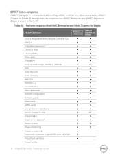
...; Remote configuration ∞ ∞ Remote update ∞ ∞ Email alerts ∞ ∞ SNMP alerts ∞ ∞ Comprehensive monitoring Virtual console (4 user) ∞ ∞ ∞ ∞2 Virtual media Crash screen capture3 ∞ ∞ ∞ ∞ Power control ∞ ∞ Power monitoring ∞ ∞ Virtual console chat ∞ Support for customer-supplied SD cards for Blades. A detailed feature comparison for iDRAC7 Enterprise and iDRAC7 Express for Blades is available for the PowerEdge...
...; Remote configuration ∞ ∞ Remote update ∞ ∞ Email alerts ∞ ∞ SNMP alerts ∞ ∞ Comprehensive monitoring Virtual console (4 user) ∞ ∞ ∞ ∞2 Virtual media Crash screen capture3 ∞ ∞ ∞ ∞ Power control ∞ ∞ Power monitoring ∞ ∞ Virtual console chat ∞ Support for customer-supplied SD cards for Blades. A detailed feature comparison for iDRAC7 Enterprise and iDRAC7 Express for Blades is available for the PowerEdge...

Technical Guide
Page 43
...; Chassis features System Setup program System messages System codes and indicators System BIOS Remove and replace procedures Troubleshooting Diagnostics Jumpers and connectors Support.Dell.com/Manuals PowerEdge Modular Systems Hardware Owner's Manual This manual provides information on the following : Initial setup steps Key system features Technical specifications System The system information label documents the system Information Label board layout and system jumper settings. PowerEdge...
...; Chassis features System Setup program System messages System codes and indicators System BIOS Remove and replace procedures Troubleshooting Diagnostics Jumpers and connectors Support.Dell.com/Manuals PowerEdge Modular Systems Hardware Owner's Manual This manual provides information on the following : Initial setup steps Key system features Technical specifications System The system information label documents the system Information Label board layout and system jumper settings. PowerEdge...


