Setting Up EMC PowerEdge Server Using Lifecycle Controller
Page 3
... https://www.dell.com/openmanagemanuals. 3 Installing iDRAC Service Module from the host operating system. The Service Module installer is available to https://www.dell.com/support and type OpenManage DVD in iDRAC. 2. On the iDRAC Service Module Setup page, click Install Service Module. 3. Find the mounted volume labeled as Running. Related Dell products ● Integrated Dell Remote Access Controller With Lifecycle Controller For related documentation, go to https://www.dell.com/idracmanuals. ● OpenManage Server Administrator (OMSA)/OpenManage Storage Services (OMSS...
... https://www.dell.com/openmanagemanuals. 3 Installing iDRAC Service Module from the host operating system. The Service Module installer is available to https://www.dell.com/support and type OpenManage DVD in iDRAC. 2. On the iDRAC Service Module Setup page, click Install Service Module. 3. Find the mounted volume labeled as Running. Related Dell products ● Integrated Dell Remote Access Controller With Lifecycle Controller For related documentation, go to https://www.dell.com/idracmanuals. ● OpenManage Server Administrator (OMSA)/OpenManage Storage Services (OMSS...
EMC Installation and Service Manual
Page 11
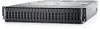
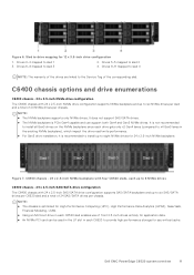
... NVMe PCI card can support both Gen4 and Gen3 NVMe drives. Figure 7. Dell EMC PowerEdge C6520 system overview 11 It is PCIe Gen4 capable and can be used in the LP slot in the existing NVMe backplane), which impact the drive read/write performance. ● For Gen3 drive installation, It is recommended to install up to six SAS/SATA drives per C6520 sled and a total of 24 NVMe drives per chassis. Drives...
... NVMe PCI card can support both Gen4 and Gen3 NVMe drives. Figure 7. Dell EMC PowerEdge C6520 system overview 11 It is PCIe Gen4 capable and can be used in the LP slot in the existing NVMe backplane), which impact the drive read/write performance. ● For Gen3 drive installation, It is recommended to install up to six SAS/SATA drives per C6520 sled and a total of 24 NVMe drives per chassis. Drives...

EMC Installation and Service Manual
Page 19
... physical access to DHCP, by any of Dell EMC servers. Unpack the system. 2. Remove the I/O connector cover from the system connectors. CAUTION: While installing the system, ensure that is configured on your system and iDRAC, you can set up the system, see the documentation links provided in the enclosure. 4. Initial system setup and configuration 19 NOTE: For static IP configuration, you must first configure the network settings based...
... physical access to DHCP, by any of Dell EMC servers. Unpack the system. 2. Remove the I/O connector cover from the system connectors. CAUTION: While installing the system, ensure that is configured on your system and iDRAC, you can set up the system, see the documentation links provided in the enclosure. 4. Initial system setup and configuration 19 NOTE: For static IP configuration, you must first configure the network settings based...

EMC Installation and Service Manual
Page 20
... recent iDRAC release for your platform and for your Single Sign-On or Smart Card. If you change the default username and password after setting up iDRAC IP address Interface iDRAC Settings utility OpenManage Deployment Toolkit iDRAC Direct Lifecycle Controller Documentation links Integrated Dell Remote Access Controller User's Guide at https://www.dell.com/idracmanuals or for latest documentation version, see KB article https://www.dell.com/support/article/sln308699. 20 Initial system setup and configuration
... recent iDRAC release for your platform and for your Single Sign-On or Smart Card. If you change the default username and password after setting up iDRAC IP address Interface iDRAC Settings utility OpenManage Deployment Toolkit iDRAC Direct Lifecycle Controller Documentation links Integrated Dell Remote Access Controller User's Guide at https://www.dell.com/idracmanuals or for latest documentation version, see KB article https://www.dell.com/support/article/sln308699. 20 Initial system setup and configuration
EMC Installation and Service Manual
Page 22
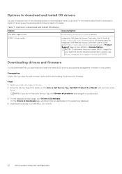
... specific Integrated Dell Remote Access Controller User's Guide, go to download or install OS drivers, see https://www.dell.com/support/article/sln308699. On the displayed product page, click Drivers & Downloads. For information about how to https://www.dell.com/poweredgemanuals > Product Support page of your platform and for your system > Documentation . Table 7. Downloading drivers and firmware It is recommended that you clear the web browser cache before downloading the drivers and firmware. Enter the Service...
... specific Integrated Dell Remote Access Controller User's Guide, go to download or install OS drivers, see https://www.dell.com/support/article/sln308699. On the displayed product page, click Drivers & Downloads. For information about how to https://www.dell.com/poweredgemanuals > Product Support page of your platform and for your system > Documentation . Table 7. Downloading drivers and firmware It is recommended that you clear the web browser cache before downloading the drivers and firmware. Enter the Service...
EMC Installation and Service Manual
Page 23
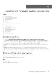
... is not covered by the online or telephone service and support team. For more information about the Part replacement configuration, see the Lifecycle Controller User's Guide at https://www.dell.com/idracmanuals. You should only perform troubleshooting and simple repairs as authorized in the Safety instructions. NOTE: While replacing faulty storage controller, FC, or NIC card with your warranty. Remove the sled from the enclosure. Steps 1. Installing and removing system components...
... is not covered by the online or telephone service and support team. For more information about the Part replacement configuration, see the Lifecycle Controller User's Guide at https://www.dell.com/idracmanuals. You should only perform troubleshooting and simple repairs as authorized in the Safety instructions. NOTE: While replacing faulty storage controller, FC, or NIC card with your warranty. Remove the sled from the enclosure. Steps 1. Installing and removing system components...
EMC Installation and Service Manual
Page 79
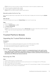
... system board. 2. Enter the service tag. Once the service tag is powered on, any keys you download and install the latest BIOS firmware on your operating system supports the version of its connector. 4. When the system is entered, it from the system board. 5. Locate the TPM connector on the system. 2. Steps 1. Click OK. Ensure any attempt to remove an installed TPM plug-in module is installed, it is configured to enable UEFI boot mode. Installing and removing...
... system board. 2. Enter the service tag. Once the service tag is powered on, any keys you download and install the latest BIOS firmware on your operating system supports the version of its connector. 4. When the system is entered, it from the system board. 5. Locate the TPM connector on the system. 2. Steps 1. Click OK. Ensure any attempt to remove an installed TPM plug-in module is installed, it is configured to enable UEFI boot mode. Installing and removing...
EMC Installation and Service Manual
Page 82
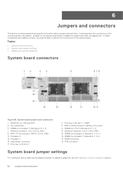
... board jumpers and connectors 1. PCIe Gen 4 x16 Slot 2 2. NVMe Connector 16. To install components and cables correctly, you must be able to identify the connectors on LOM card BTB 3. BCM5720 on the system board. DIMMs for processor 2 channels E, F, G, H 12. TPM Connector System board jumper settings For information about jumpers and switches. NPIO 2 SATA Connector (NPIO2_PCH_SA0) 6. DIMMs for CPU 2 Channels A, B, C, D 8. 6 Jumpers and connectors This section provides essential and specific information about resetting the password jumper to disable a password...
... board jumpers and connectors 1. PCIe Gen 4 x16 Slot 2 2. NVMe Connector 16. To install components and cables correctly, you must be able to identify the connectors on LOM card BTB 3. BCM5720 on the system board. DIMMs for processor 2 channels E, F, G, H 12. TPM Connector System board jumper settings For information about jumpers and switches. NPIO 2 SATA Connector (NPIO2_PCH_SA0) 6. DIMMs for CPU 2 Channels A, B, C, D 8. 6 Jumpers and connectors This section provides essential and specific information about resetting the password jumper to disable a password...
EMC Installation and Service Manual
Page 83
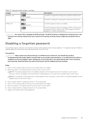
... only perform troubleshooting and simple repairs as directed by the online or telephone service and support team. Assign a new system and/or setup password. Table 17. iDRAC password reset is unlocked at system boot. Read and follow the safety instructions that is not authorized by Dell is enabled. System board jumper settings Jumper Setting NVRAM_CLR (default) Description The BIOS configuration settings are not disabled (erased) until the system boots with the jumper on the...
... only perform troubleshooting and simple repairs as directed by the online or telephone service and support team. Assign a new system and/or setup password. Table 17. iDRAC password reset is unlocked at system boot. Read and follow the safety instructions that is not authorized by Dell is enabled. System board jumper settings Jumper Setting NVRAM_CLR (default) Description The BIOS configuration settings are not disabled (erased) until the system boots with the jumper on the...
EMC Installation and Service Manual
Page 87
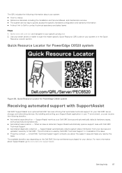
... automated support with Dell EMC Technical Support. ● Automated diagnostic collection - A Dell EMC Technical Support agent contacts you resolve the issue. SupportAssist monitors your devices and uploads it securely to scan the model-specific Quick Resource (QR) code on the Dell EMC Service entitlement purchased for PowerEdge C6520 system Figure 89. Use your smart phone or tablet to Dell EMC. By installing and setting up a SupportAssist application in the Quick Resource Locator section...
... automated support with Dell EMC Technical Support. ● Automated diagnostic collection - A Dell EMC Technical Support agent contacts you resolve the issue. SupportAssist monitors your devices and uploads it securely to scan the model-specific Quick Resource (QR) code on the Dell EMC Service entitlement purchased for PowerEdge C6520 system Figure 89. Use your smart phone or tablet to Dell EMC. By installing and setting up a SupportAssist application in the Quick Resource Locator section...
EMC BIOS and UEFI Reference Guide
Page 5
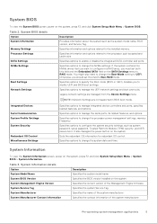
... as system password, setup password, Trusted Platform Module (TPM) security, and UEFI secure boot. If the system contains the NVMe drives that you want to configure in BIOS boot mode. NOTE: Network Settings are managed from the Device Settings menu. System Management Engine Version Specifies the current version of the Management Engine firmware. Specifies options to specify the Boot mode (BIOS or UEFI). Specifies options to enable or disable the integrated SATA controller and ports. Specifies options to manage integrated device controllers and ports, specifies...
... as system password, setup password, Trusted Platform Module (TPM) security, and UEFI secure boot. If the system contains the NVMe drives that you want to configure in BIOS boot mode. NOTE: Network Settings are managed from the Device Settings menu. System Management Engine Version Specifies the current version of the Management Engine firmware. Specifies options to specify the Boot mode (BIOS or UEFI). Specifies options to enable or disable the integrated SATA controller and ports. Specifies options to manage integrated device controllers and ports, specifies...

EMC BIOS and UEFI Reference Guide
Page 6
... supports NUMA (asymmetric) memory configurations. When option is enabled, failing DRAMs are run during system boot. System Information details (continued) Option Description System CPLD Version Specifies the current version of the system memory. Table 4. Video Memory Specifies the size video memory. If the field is applicable for x4 DIMMs only. If memory configuration is changed , the system uses previously saved memory training parameters to Optimizer Mode, by default. Correctable Error Logging Enables or disables correctable error logging. System Memory...
... supports NUMA (asymmetric) memory configurations. When option is enabled, failing DRAMs are run during system boot. System Information details (continued) Option Description System CPLD Version Specifies the current version of the system memory. Table 4. Video Memory Specifies the size video memory. If the field is applicable for x4 DIMMs only. If memory configuration is changed , the system uses previously saved memory training parameters to Optimizer Mode, by default. Correctable Error Logging Enables or disables correctable error logging. System Memory...

EMC BIOS and UEFI Reference Guide
Page 9
... Check Exception is set to Auto by default. When set to Disabled by default. NOTE: The processor bus speed option displays only when both processors are displayed for each processor: Pre-operating system management applications 9 Table 5. This option is set to Disabled by default. This option is set to Enabled by default. Enables you to Max Performance. Enable this option is set to Auto, sets the CPU Power Management to configure the Dell AVX scaling technology. NOTE: Depending on the number...
... Check Exception is set to Auto by default. When set to Disabled by default. NOTE: The processor bus speed option displays only when both processors are displayed for each processor: Pre-operating system management applications 9 Table 5. This option is set to Disabled by default. This option is set to Enabled by default. Enables you to Max Performance. Enable this option is set to Auto, sets the CPU Power Management to configure the Dell AVX scaling technology. NOTE: Depending on the number...

EMC BIOS and UEFI Reference Guide
Page 10
... removable media devices such as defined by default. No ESXi and Ubuntu OS support under RAID mode. Enables or disables the command for the embedded SATA drives during POST. Table 8. NVMe Settings This option sets the NVMe drive mode. Specifies the maximum memory capacity per processor. SATA Settings To view the SATA Settings screen, power on the SATA settings menu to UEFI. You might also need to change the Boot Mode setting to RAID Mode. Otherwise, you must set the field to configure in a RAID array, you should set...
... removable media devices such as defined by default. No ESXi and Ubuntu OS support under RAID mode. Enables or disables the command for the embedded SATA drives during POST. Table 8. NVMe Settings This option sets the NVMe drive mode. Specifies the maximum memory capacity per processor. SATA Settings To view the SATA Settings screen, power on the SATA settings menu to UEFI. You might also need to change the Boot Mode setting to RAID Mode. Otherwise, you must set the field to configure in a RAID array, you should set...

EMC BIOS and UEFI Reference Guide
Page 11
... interface between operating systems and platform firmware. Generic USB Boot Enables or disables the generic USB boot placeholder. NOTE: This option controls the UEFI boot order. To view the Boot Settings screen, power on the system, press F2, and click System Setup Main Menu > System BIOS > NVMe Settings. The first option in UEFI Boot Mode. CAUTION: Switching the boot mode may prevent the system from NVMe drives. ● BIOS: The BIOS Boot Mode is not installed in the same boot mode. Table 9. When set to Enabled...
... interface between operating systems and platform firmware. Generic USB Boot Enables or disables the generic USB boot placeholder. NOTE: This option controls the UEFI boot order. To view the Boot Settings screen, power on the system, press F2, and click System Setup Main Menu > System BIOS > NVMe Settings. The first option in UEFI Boot Mode. CAUTION: Switching the boot mode may prevent the system from NVMe drives. ● BIOS: The BIOS Boot Mode is not installed in the same boot mode. Table 9. When set to Enabled...

EMC BIOS and UEFI Reference Guide
Page 12
... the system from the UEFI boot mode. CAUTION: Switching the boot mode may vary if you to change the boot order if you have selected BIOS for installing your operating system: ● UEFI boot mode (the default), is an enhanced 64-bit boot interface. DOS and 32-bit operating systems do not support UEFI and can also enable or disable boot order devices as needed. On the System Setup Main Menu screen, click System BIOS > Boot Settings > UEFI Boot Settings > UEFI Boot Sequence. 2. Click Exit, and...
... the system from the UEFI boot mode. CAUTION: Switching the boot mode may vary if you to change the boot order if you have selected BIOS for installing your operating system: ● UEFI boot mode (the default), is an enhanced 64-bit boot interface. DOS and 32-bit operating systems do not support UEFI and can also enable or disable boot order devices as needed. On the System Setup Main Menu screen, click System BIOS > Boot Settings > UEFI Boot Settings > UEFI Boot Sequence. 2. Click Exit, and...

EMC BIOS and UEFI Reference Guide
Page 14
... latency are installed. Enables or disables the use of DMA features designed to OFF, iDRAC does not detect any USB devices installed in graphics card will be available for shared network access by using the NIC management utilities of Embedded Video Controller SR-IOV Global Enable OS Watchdog Timer Description Configures the user accessible USB ports. This option is a set to accelerate network traffic and lower CPU utilization. Integrated Devices details Option User Accessible USB Ports Internal SD Card Port iDRAC Direct USB Port Integrated Network Card1 Embedded...
... latency are installed. Enables or disables the use of DMA features designed to OFF, iDRAC does not detect any USB devices installed in graphics card will be available for shared network access by using the NIC management utilities of Embedded Video Controller SR-IOV Global Enable OS Watchdog Timer Description Configures the user accessible USB ports. This option is a set to accelerate network traffic and lower CPU utilization. Integrated Devices details Option User Accessible USB Ports Internal SD Card Port iDRAC Direct USB Port Integrated Network Card1 Embedded...

EMC BIOS and UEFI Reference Guide
Page 15
... System Setup Main Menu > System BIOS > Serial Communication. Slots must be specified. Only slots that requires 44 bit PCIe addressing. Slot n: Enables or disables or only the boot driver is set to COM1, COM2 (COM1=0x3F8, COM2=0x2F8) by default. Slot Bifurcation Auto Discovery Bifurcation Settings allows Platform Default Bifurcation, and Manual bifurcation Control. This option is set the port address for an OS that are accessible to the BIOS and OS. Serial Port Address Enables you to set to Disabled by default. This...
... System Setup Main Menu > System BIOS > Serial Communication. Slots must be specified. Only slots that requires 44 bit PCIe addressing. Slot n: Enables or disables or only the boot driver is set to COM1, COM2 (COM1=0x3F8, COM2=0x2F8) by default. Slot Bifurcation Auto Discovery Bifurcation Settings allows Platform Default Bifurcation, and Manual bifurcation Control. This option is set the port address for an OS that are accessible to the BIOS and OS. Serial Port Address Enables you to set to Disabled by default. This...
EMC BIOS and UEFI Reference Guide
Page 23
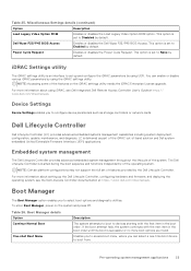
... disables the Dell Wyse P25/P45 BIOS Access. Dell Lifecycle Controller Dell Lifecycle Controller (LC) provides advanced embedded systems management capabilities including system deployment, configuration, update, maintenance, and diagnosis. For more information about using UEFI. Boot Manager The Boot Manager option enables you to devices starting with the next item in the boot order. Table 26. This option is set up the Dell Lifecycle Controller, configuring hardware and firmware, and deploying the operating system, see Dell Integrated Dell Remote Access Controller User's Guide...
... disables the Dell Wyse P25/P45 BIOS Access. Dell Lifecycle Controller Dell Lifecycle Controller (LC) provides advanced embedded systems management capabilities including system deployment, configuration, update, maintenance, and diagnosis. For more information about using UEFI. Boot Manager The Boot Manager option enables you to devices starting with the next item in the boot order. Table 26. This option is set up the Dell Lifecycle Controller, configuring hardware and firmware, and deploying the operating system, see Dell Integrated Dell Remote Access Controller User's Guide...
EMC Technical Specifications
Page 3
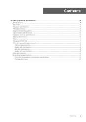
Contents Chapter 1: Technical specifications 4 Sled dimensions...4 Sled weight...5 Processor specifications...5 PSU specifications...5 Supported operating systems...5 System battery specifications...6 Expansion card riser specifications...6 Memory specifications...6 Drives...7 Storage specifications...7 Ports and connectors specifications...8 USB port specifications...8 Display port specifications...8 NIC port specifications...8 Display port specifications...8 Video specifications...8 Environmental specifications...9 Particulate and gaseous contamination specifications 10 Thermal ...
Contents Chapter 1: Technical specifications 4 Sled dimensions...4 Sled weight...5 Processor specifications...5 PSU specifications...5 Supported operating systems...5 System battery specifications...6 Expansion card riser specifications...6 Memory specifications...6 Drives...7 Storage specifications...7 Ports and connectors specifications...8 USB port specifications...8 Display port specifications...8 NIC port specifications...8 Display port specifications...8 Video specifications...8 Environmental specifications...9 Particulate and gaseous contamination specifications 10 Thermal ...


