Hardware Owners Manual
Page 8
... Mezzanine Card 205 Installing the 1GbE Mezzanine Card 207 Removing the 10GbE Mezzanine Card 208 Installing the 10GbE Mezzanine Card 211 Mezzanine-Card Bridge Board 212 Removing the Mezzanine-Card Bridge Board 212 Installing the Mezzanine-Card Bridge Board 213 System Memory 214 Memory Slot Features 214 Supported Memory Module Configuration 214 Removing the Memory Modules 216 Installing the Memory Modules 218 System Battery 220 Replacing the System Battery 220 System Board 222 Removing a System Board 222 Installing a System Board 224 Cable Routing for Onboard SATA Cables (1U...
... Mezzanine Card 205 Installing the 1GbE Mezzanine Card 207 Removing the 10GbE Mezzanine Card 208 Installing the 10GbE Mezzanine Card 211 Mezzanine-Card Bridge Board 212 Removing the Mezzanine-Card Bridge Board 212 Installing the Mezzanine-Card Bridge Board 213 System Memory 214 Memory Slot Features 214 Supported Memory Module Configuration 214 Removing the Memory Modules 216 Installing the Memory Modules 218 System Battery 220 Replacing the System Battery 220 System Board 222 Removing a System Board 222 Installing a System Board 224 Cable Routing for Onboard SATA Cables (1U...
Hardware Owners Manual
Page 52
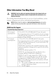
... temperature range, ambient temperature warnings may be reported in the System Event Log. NOTE: 1U and 2U nodes support the 130W (8 core), 130W (4 core) and 135W processors with the specific configurations of HDD in other documents. NOTE: No cold start up your system. Warranty information may be included within this document or as a separate document. dew point. NOTE: The operating temperature specification is for updates on dell.com/support/manuals...
... temperature range, ambient temperature warnings may be reported in the System Event Log. NOTE: 1U and 2U nodes support the 130W (8 core), 130W (4 core) and 135W processors with the specific configurations of HDD in other documents. NOTE: No cold start up your system. Warranty information may be included within this document or as a separate document. dew point. NOTE: The operating temperature specification is for updates on dell.com/support/manuals...

Hardware Owners Manual
Page 71
...; BMC LAN Port Configuration: Dedicated-NIC DHCP Enabled: Disabled or Enabled (Enabled if DHCP server support) IP Address: 192.168.001.003 Subnet Mask: 255.255.255.000 Gateway Address: 000.000.000.000 To do this, see "Set BMC LAN Configuration" on page 100. For location of Shared-NIC, perform the following settings: Remote Access: enabled Serial port number: COM2 Serial Port Mode: 115200 8, n, 1 Flow Control: None Redirection After BIOS POST: Always...
...; BMC LAN Port Configuration: Dedicated-NIC DHCP Enabled: Disabled or Enabled (Enabled if DHCP server support) IP Address: 192.168.001.003 Subnet Mask: 255.255.255.000 Gateway Address: 000.000.000.000 To do this, see "Set BMC LAN Configuration" on page 100. For location of Shared-NIC, perform the following settings: Remote Access: enabled Serial port number: COM2 Serial Port Mode: 115200 8, n, 1 Flow Control: None Redirection After BIOS POST: Always...

Hardware Owners Manual
Page 87
... (Disabled default) Description Auto - Sets the SATA link rate at maximum as 6.0 Gbps. 1.5 Gbps - Off - Auto - Sets the 2nd Serial ATA drive controller to initiate link power management transitions. Sets the 6th Serial ATA drive controller to Auto (enabled if present, POST error if not present). Sets the 2nd Serial ATA drive controller to off . Auto -Sets the 6th Serial ATA drive controller to Auto (enabled if present, POST error if not present). Sets the SATA link rate at minimum as 3.0 Gbps. For power consumption...
... (Disabled default) Description Auto - Sets the SATA link rate at maximum as 6.0 Gbps. 1.5 Gbps - Off - Auto - Sets the 2nd Serial ATA drive controller to initiate link power management transitions. Sets the 6th Serial ATA drive controller to Auto (enabled if present, POST error if not present). Sets the 2nd Serial ATA drive controller to off . Auto -Sets the 6th Serial ATA drive controller to Auto (enabled if present, POST error if not present). Sets the SATA link rate at minimum as 3.0 Gbps. For power consumption...

Hardware Owners Manual
Page 94
... the given PCI-E Link of ASPM supported on the NBSB. Controls the level of port11. Option Mezzanine Slot ASPM (Disabled default) NB-SB Link ASPM (L1 default) PCI Slot Configuration Description Disabled - L1 entry is disabled. Option PCIe Slot (Enabled default) Description This feature will allow user to enable/disable PCI-E Slot and without option ROM initialization. 94 | Using the System Setup Program All entry is enabled. Controls the level of ASPM supported on the PCI-E Link of ASPM supported on the...
... the given PCI-E Link of ASPM supported on the NBSB. Controls the level of port11. Option Mezzanine Slot ASPM (Disabled default) NB-SB Link ASPM (L1 default) PCI Slot Configuration Description Disabled - L1 entry is disabled. Option PCIe Slot (Enabled default) Description This feature will allow user to enable/disable PCI-E Slot and without option ROM initialization. 94 | Using the System Setup Program All entry is enabled. Controls the level of ASPM supported on the PCI-E Link of ASPM supported on the...

Hardware Owners Manual
Page 96
Installs or changes the password. 96 | Using the System Setup Program Installs or changes the password. Scroll to this item and press Enter to set the security parameters. Security Menu This page enables you to view the following screen: Option Supervisor Password User Password Change Supervisor Password Change User Password Description Displays whether the supervisor password is installed or not. Displays whether the user password is installed or not.
Installs or changes the password. 96 | Using the System Setup Program Installs or changes the password. Scroll to this item and press Enter to set the security parameters. Security Menu This page enables you to view the following screen: Option Supervisor Password User Password Change Supervisor Password Change User Password Description Displays whether the supervisor password is installed or not. Displays whether the user password is installed or not.

Hardware Owners Manual
Page 99
... BMC firmware version. NIC2 MAC Address Displays the NIC2 MAC address. Set BMC LAN Configuration Inputs for IPMI driver installation. Remote Access Configuration Configures Remote Access. Power On - ACPI SPMI Table (Enabled default) Disabled - Power Staggering AC Recovery (Immediate default) Power Button (Enabled default) Sets the Power Staggering AC Recovery time to turn off . Default, Enables Power Button to immediate/Random/User Defined mode. NIC1 MAC Address Displays the NIC1 MAC address. Enabled - Enables the ACPI SPMI Table for Set LAN Configuration command...
... BMC firmware version. NIC2 MAC Address Displays the NIC2 MAC address. Set BMC LAN Configuration Inputs for IPMI driver installation. Remote Access Configuration Configures Remote Access. Power On - ACPI SPMI Table (Enabled default) Disabled - Power Staggering AC Recovery (Immediate default) Power Button (Enabled default) Sets the Power Staggering AC Recovery time to turn off . Default, Enables Power Button to immediate/Random/User Defined mode. NIC1 MAC Address Displays the NIC1 MAC address. Enabled - Enables the ACPI SPMI Table for Set LAN Configuration command...

Hardware Owners Manual
Page 101
Sets BMC LAN Gateway address. Remote Access Configuration Select Remote Access Configuration to get LAN IP from Static/ DHCP mode. Enables or disables IPv6 internet protocol support. Sets BMC LAN subnet mask. Sets BMC LAN IP address. Option (Shared-NIC default) BMC NIC IP Source (DHCP default) IP Address Subnet Mask Gateway Address IPv6 Mode (Disabled default) Description Sets BMC LAN to view the following submenu: Using the System Setup Program | 101
Sets BMC LAN Gateway address. Remote Access Configuration Select Remote Access Configuration to get LAN IP from Static/ DHCP mode. Enables or disables IPv6 internet protocol support. Sets BMC LAN subnet mask. Sets BMC LAN IP address. Option (Shared-NIC default) BMC NIC IP Source (DHCP default) IP Address Subnet Mask Gateway Address IPv6 Mode (Disabled default) Description Sets BMC LAN to view the following submenu: Using the System Setup Program | 101

Hardware Owners Manual
Page 124
...Serial Port Mode Console Redirection baud rate will be set to generate NMI when PCI-E uncorrectable errors occur. 124 | Using the System Setup Program IPv6 Mode Disables IPv6 internet protocol support. IPv6 AutoConfig Enables IPv6 auto configuration. IPv6 Mode Enables IPv6 internet protocol support. Flow Control Flow Control Flow Control Terminal Type VT-UTF8 Combo Key Support VT-UTF8 Combo Key Support Remote access flow controls by software. Enables VT-UTF8 Combination Key Support for ANSI/VT100 terminals. Event logging Event logging NMI on Error Disables BIOS to log...
...Serial Port Mode Console Redirection baud rate will be set to generate NMI when PCI-E uncorrectable errors occur. 124 | Using the System Setup Program IPv6 Mode Disables IPv6 internet protocol support. IPv6 AutoConfig Enables IPv6 auto configuration. IPv6 Mode Enables IPv6 internet protocol support. Flow Control Flow Control Flow Control Terminal Type VT-UTF8 Combo Key Support VT-UTF8 Combo Key Support Remote access flow controls by software. Enables VT-UTF8 Combination Key Support for ANSI/VT100 terminals. Event logging Event logging NMI on Error Disables BIOS to log...

Hardware Owners Manual
Page 136
Setup Menu Setting Setup Page Setting Memory Configuration SATA Configuration C State C1E State C6 State C7 State Direct Cache Access Hyper-Threading Technology Adjacent Cache Line Prefetch Hardware Prefetcher DCU Streamer Prefetcher DCU IP Prefetcher Memory Frequency Memory Turbo Mode Memory Throttling Mode Memory Operating Voltage Embedded SATA Link State Power Saving Features PCI PCI-E Slot ASPM Configuration Onboard LAN ASPM Mezzing Slot ASPM NB-SB Link ASPM PCI-E Generation Maximum Performance (48DB) Option D4 Token Disabled 024C Disabled 02A2 Disabled 480A Disabled ...
Setup Menu Setting Setup Page Setting Memory Configuration SATA Configuration C State C1E State C6 State C7 State Direct Cache Access Hyper-Threading Technology Adjacent Cache Line Prefetch Hardware Prefetcher DCU Streamer Prefetcher DCU IP Prefetcher Memory Frequency Memory Turbo Mode Memory Throttling Mode Memory Operating Voltage Embedded SATA Link State Power Saving Features PCI PCI-E Slot ASPM Configuration Onboard LAN ASPM Mezzing Slot ASPM NB-SB Link ASPM PCI-E Generation Maximum Performance (48DB) Option D4 Token Disabled 024C Disabled 02A2 Disabled 480A Disabled ...

Hardware Owners Manual
Page 153
... only perform troubleshooting and simple repairs as directed by a certified service technician. Heat Sinks Removing the Heat Sink CAUTION: Many repairs may only be done by the online or telephone service and support team. NOTE: Place the foolproof pins of the Installed Air Baffle 2 Replace the system-board assembly. Figure 3-12. See "Installing a System-Board Assembly" on page 150. The Top View of two processor heatsinks...
... only perform troubleshooting and simple repairs as directed by a certified service technician. Heat Sinks Removing the Heat Sink CAUTION: Many repairs may only be done by the online or telephone service and support team. NOTE: Place the foolproof pins of the Installed Air Baffle 2 Replace the system-board assembly. Figure 3-12. See "Installing a System-Board Assembly" on page 150. The Top View of two processor heatsinks...
Hardware Owners Manual
Page 157
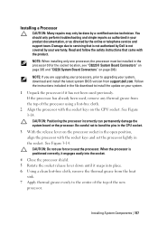
...-free cloth, remove the thermal grease from support.dell.com. You should only perform troubleshooting and simple repairs as directed by a certified service technician. Follow the instructions included in the file download to the center of the top of the processor using a lint-free cloth. 2 Align the processor with the socket keys and set the processor lightly in the processor 0 (for the socket location, see "C6220 II System Board Connectors" on...
...-free cloth, remove the thermal grease from support.dell.com. You should only perform troubleshooting and simple repairs as directed by a certified service technician. Follow the instructions included in the file download to the center of the top of the processor using a lint-free cloth. 2 Align the processor with the socket keys and set the processor lightly in the processor 0 (for the socket location, see "C6220 II System Board Connectors" on...
Hardware Owners Manual
Page 291
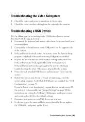
... the problem is resolved, replace the faulty keyboard/mouse. Troubleshooting the Video Subsystem 1 Check the system and power connections to the monitor. 2 Check the video interface cabling from the system. 6 Restart the system and, if your keyboard is not functioning, you can also use remote access. Verify that all attached USB devices and disconnect them . 2 Connect the keyboard/mouse to the default settings. 7 Reconnect and power on setting the NVRAM_CLR jumper inside your...
... the problem is resolved, replace the faulty keyboard/mouse. Troubleshooting the Video Subsystem 1 Check the system and power connections to the monitor. 2 Check the video interface cabling from the system. 6 Restart the system and, if your keyboard is not functioning, you can also use remote access. Verify that all attached USB devices and disconnect them . 2 Connect the keyboard/mouse to the default settings. 7 Reconnect and power on setting the NVRAM_CLR jumper inside your...
Hardware Owners Manual
Page 292
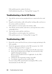
... system messages pertaining to the serial port. 2 Swap the serial interface cable with a comparable device. 4 Turn on the system and the serial device. Remove and reinstall the drivers if applicable. If you are using a NIC card instead of an integrated NIC, see the documentation for any peripheral devices connected to the NIC controller. 2 Check the appropriate indicator on page 323. If the problem persists, see "Getting Help" on the switch or hub. See "LAN Indicators (Management Port...
... system messages pertaining to the serial port. 2 Swap the serial interface cable with a comparable device. 4 Turn on the system and the serial device. Remove and reinstall the drivers if applicable. If you are using a NIC card instead of an integrated NIC, see the documentation for any peripheral devices connected to the NIC controller. 2 Check the appropriate indicator on page 323. If the problem persists, see "Getting Help" on the switch or hub. See "LAN Indicators (Management Port...

Hardware Owners Manual
Page 293
... "Using the System Setup Program" on page 65. 5 Ensure that the NICs, hubs, and switches on page 137. Hard drives SAS backplane Expansion-card Power supplies Fans Processors and heat sinks Memory modules 4 Let the system dry thoroughly for each network device. 6 Ensure that all network cables are of the proper type and do not exceed the maximum length. You should only perform troubleshooting and simple repairs...
... "Using the System Setup Program" on page 65. 5 Ensure that the NICs, hubs, and switches on page 137. Hard drives SAS backplane Expansion-card Power supplies Fans Processors and heat sinks Memory modules 4 Let the system dry thoroughly for each network device. 6 Ensure that all network cables are of the proper type and do not exceed the maximum length. You should only perform troubleshooting and simple repairs...

Hardware Owners Manual
Page 294
... "Opening the System" on page 323. 8 If the system starts properly, shut down the system and reinstall the expansion card that all cables are properly installed: Expansion-card assembly Power supplies Fans Processors and heat sinks Memory modules Hard-drive carriers 4 Ensure that you removed in your warranty. 5 Reinstall the components you removed. See "Closing the System" on page 231. 6 If the system fails...
... "Opening the System" on page 323. 8 If the system starts properly, shut down the system and reinstall the expansion card that all cables are properly installed: Expansion-card assembly Power supplies Fans Processors and heat sinks Memory modules Hard-drive carriers 4 Ensure that you removed in your warranty. 5 Reinstall the components you removed. See "Closing the System" on page 231. 6 If the system fails...

Hardware Owners Manual
Page 300
... required device drivers for a LSI 9210-8i HBA Card or LSI SAS 2008 mezzanine card. See the operating system documentation for the RAID array. Exit the configuration utility and allow the system to boot to servicing that came with the host adapter for information about the configuration utility. Troubleshooting a Hard Drive CAUTION: Many repairs may only be done by the online or telephone service and support team. See "Removing a System-Board Assembly" on the hard drive. See "Using...
... required device drivers for a LSI 9210-8i HBA Card or LSI SAS 2008 mezzanine card. See the operating system documentation for the RAID array. Exit the configuration utility and allow the system to boot to servicing that came with the host adapter for information about the configuration utility. Troubleshooting a Hard Drive CAUTION: Many repairs may only be done by the online or telephone service and support team. See "Removing a System-Board Assembly" on the hard drive. See "Using...
Hardware Owners Manual
Page 328
...features, 13 support C6220 fresh air, 52 C6220 II fresh air f, 59 contacting Dell, 323 system closing, 231 opening, 230 system board installing, 224 jumper settings, 320, 321 removing, 222 system board assembly installing, 150 removing, 148, 149 system cooling troubleshooting, 296 system features accessing, 13 328 | Index system setup LAN configuration, 100 memory configuration, 83 PCI configuration, 88 power management, 76 processor configuration, 78 remote access configuration, 101 SATA configuration, 85 USB configuration, 95 T telephone number, 323 troubleshooting cooling fans, 297 damaged...
...features, 13 support C6220 fresh air, 52 C6220 II fresh air f, 59 contacting Dell, 323 system closing, 231 opening, 230 system board installing, 224 jumper settings, 320, 321 removing, 222 system board assembly installing, 150 removing, 148, 149 system cooling troubleshooting, 296 system features accessing, 13 328 | Index system setup LAN configuration, 100 memory configuration, 83 PCI configuration, 88 power management, 76 processor configuration, 78 remote access configuration, 101 SATA configuration, 85 USB configuration, 95 T telephone number, 323 troubleshooting cooling fans, 297 damaged...
Using the Baseboard Management Controller
Page 5
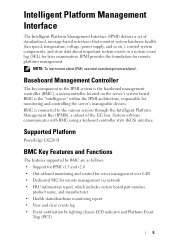
... Dedicated NIC for monitoring and controlling the server's manageable devices. Supported Platform PowerEdge C6220 II BMC Key Features and Functions The features supported by lighting chassis LED indicator and Platform Event Trap (PET) Template Last Updated - 2/7/2007 5 IPMI provides the foundation for later examination. Intelligent Platform Management Interface The Intelligent Platform Management Interface (IPMI) defines a set of standardized, message-based interfaces that monitor system hardware health (fan speed, temperature, voltage, power supply, and so on the server's system board...
... Dedicated NIC for monitoring and controlling the server's manageable devices. Supported Platform PowerEdge C6220 II BMC Key Features and Functions The features supported by lighting chassis LED indicator and Platform Event Trap (PET) Template Last Updated - 2/7/2007 5 IPMI provides the foundation for later examination. Intelligent Platform Management Interface The Intelligent Platform Management Interface (IPMI) defines a set of standardized, message-based interfaces that monitor system hardware health (fan speed, temperature, voltage, power supply, and so on the server's system board...

Using the Baseboard Management Controller
Page 32
... 1-18. Power Control Operations Power On System Option Select this button to apply the changes. 32 Apply Changes Button Use this option to perform an immediate shutdown of the server. Power Control Item Description Power Status Power Status Displays the server power status. Hard Reset (Restart) Select this option to power up the server. Control The Control submenu lets you to remotely reset the server without powering off . Power Off System Option Select this option to view the server's power status. FILE LOCATION: D:\Projects\User Guide\Server\Dell\C6220II\BMC...
... 1-18. Power Control Operations Power On System Option Select this button to apply the changes. 32 Apply Changes Button Use this option to perform an immediate shutdown of the server. Power Control Item Description Power Status Power Status Displays the server power status. Hard Reset (Restart) Select this option to power up the server. Control The Control submenu lets you to remotely reset the server without powering off . Power Off System Option Select this option to view the server's power status. FILE LOCATION: D:\Projects\User Guide\Server\Dell\C6220II\BMC...

