Microprocessor Upgrade Installation Guide
Page 3
... your Installation and Troubleshooting Guide). NOTICE: Before you can add secondary microprocessors or replace microprocessors in the primary microprocessor socket. CAUTION: Before you perform this procedure, read the safety instructions in speed and functionality, you add or replace a microprocessor, check the latest system BIOS information on the Dell Support website at support.dell.com, and upgrade the BIOS if necessary. Microprocessor Upgrade Installation Guide 1-1 Each microprocessor and its associated cache memory...
... your Installation and Troubleshooting Guide). NOTICE: Before you can add secondary microprocessors or replace microprocessors in the primary microprocessor socket. CAUTION: Before you perform this procedure, read the safety instructions in speed and functionality, you add or replace a microprocessor, check the latest system BIOS information on the Dell Support website at support.dell.com, and upgrade the BIOS if necessary. Microprocessor Upgrade Installation Guide 1-1 Each microprocessor and its associated cache memory...
Microprocessor Upgrade Installation Guide
Page 4
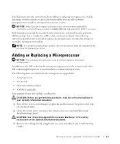
... extremely hot. Bending the pins can remove the heat sink without removing the fan. NOTICE: Be careful not to the fully open position (see your Installation and Troubleshooting Guide for the new microprocessor. b Remove the heat sink. NOTICE: Be careful not to prevent the thermal interface material from being damaged or contaminated. The heat sink is mounted on removing a cooling fan, see Figure 1-1). See your Installation and Troubleshooting Guide...
... extremely hot. Bending the pins can remove the heat sink without removing the fan. NOTICE: Be careful not to the fully open position (see your Installation and Troubleshooting Guide for the new microprocessor. b Remove the heat sink. NOTICE: Be careful not to prevent the thermal interface material from being damaged or contaminated. The heat sink is mounted on removing a cooling fan, see Figure 1-1). See your Installation and Troubleshooting Guide...
Microprocessor Upgrade Installation Guide
Page 5
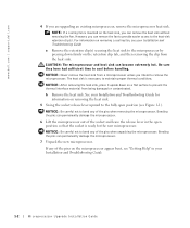
... aligned, set the microprocessor lightly in the socket and ensure that all pins are matched with the correct holes in the socket. When the microprocessor is fully seated in the fully open position. Be careful not to use force (...Removing and Replacing the Microprocessor pin-1 locators microprocessor microprocessor socket NOTICE: Positioning the microprocessor incorrectly can permanently damage the microprocessor and the system when you turn on the microprocessor go into the socket with pin 1 on the microprocessor with minimal pressure. Figure 1-1. Because the system uses...
... aligned, set the microprocessor lightly in the socket and ensure that all pins are matched with the correct holes in the socket. When the microprocessor is fully seated in the fully open position. Be careful not to use force (...Removing and Replacing the Microprocessor pin-1 locators microprocessor microprocessor socket NOTICE: Positioning the microprocessor incorrectly can permanently damage the microprocessor and the system when you turn on the microprocessor go into the socket with pin 1 on the microprocessor with minimal pressure. Figure 1-1. Because the system uses...
Microprocessor Upgrade Installation Guide
Page 6
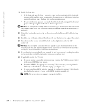
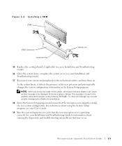
... from the upgrade kit. NOTE: The system does not support mismatched VRMs. 1-4 Microprocessor Upgrade Installation Guide www.dell.com | support.dell.com 9 Install the heat sink. • If the heat sink provided has a protective cover on the underside of the heat sink, remove and discard the cover to ensure that the latches at each end of the connector engage (see your Installation and Troubleshooting Guide. 13 If a cooling fan is provided...
... from the upgrade kit. NOTE: The system does not support mismatched VRMs. 1-4 Microprocessor Upgrade Installation Guide www.dell.com | support.dell.com 9 Install the heat sink. • If the heat sink provided has a protective cover on the underside of the heat sink, remove and discard the cover to ensure that the latches at each end of the connector engage (see your Installation and Troubleshooting Guide. 13 If a cooling fan is provided...
Microprocessor Upgrade Installation Guide
Page 7
... your Installation and Troubleshooting Guide). 16 Close the system doors, or replace the system cover (see your Installation and Troubleshooting Guide). 17 Reconnect your User's Guide. 19 Run the system diagnostics to verify that the microprocessor categories match the new system configuration. NOTE: After you access the inside of the new processor and automatically changes the system configuration information in the system's nonvolatile random-access memory (NVRAM). To clear this message log, see...
... your Installation and Troubleshooting Guide). 16 Close the system doors, or replace the system cover (see your Installation and Troubleshooting Guide). 17 Reconnect your User's Guide. 19 Run the system diagnostics to verify that the microprocessor categories match the new system configuration. NOTE: After you access the inside of the new processor and automatically changes the system configuration information in the system's nonvolatile random-access memory (NVRAM). To clear this message log, see...

Information Update
Page 29
5 [Serial Console Redirection] 6 [Enabled] 7 : (Windows HyperTerminal ) 8 9 10 [Yes] Dell Dell Windows NT® Microsoft Windows 95 Windows 98 Dell OpenManage Server Assistant CD : and Troubleshooting Guide Dell PXE (Preboot Execution Environment) PXE (Preboot Execution Environment) Dell PowerEdge 350 Systems Installation : PowerEdge 350 PXE 1 PXE 1 2 Hit if you want to run setup 5-3
5 [Serial Console Redirection] 6 [Enabled] 7 : (Windows HyperTerminal ) 8 9 10 [Yes] Dell Dell Windows NT® Microsoft Windows 95 Windows 98 Dell OpenManage Server Assistant CD : and Troubleshooting Guide Dell PXE (Preboot Execution Environment) PXE (Preboot Execution Environment) Dell PowerEdge 350 Systems Installation : PowerEdge 350 PXE 1 PXE 1 2 Hit if you want to run setup 5-3
Memory Module Installation Information Update
Page 5
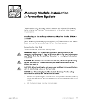
... microprocessor. support.dell.com Information Update 1-1 The information in the DIMM3 socket on the heat sink clip tab, and then releasing the clip from the opposite side of the socket. 2. When replacing or installing a memory module in this document applies to the microprocessor socket by pressing on your system board, you must first remove the heat sink from the microprocessor. To remove heat sink...
... microprocessor. support.dell.com Information Update 1-1 The information in the DIMM3 socket on the heat sink clip tab, and then releasing the clip from the opposite side of the socket. 2. When replacing or installing a memory module in this document applies to the microprocessor socket by pressing on your system board, you must first remove the heat sink from the microprocessor. To remove heat sink...

System Diagnostics Information Update
Page 1
... the 850-megahertz (MHz) microprocessor is installed and the system diagnostics are run, floating point unit (FPU) exception errors are false errors and should be used in this document is strictly forbidden. Printed in trademarks and trade names other than its own...document to refer to change without the written permission of Dell Computer Corporation. Trademarks used in this text: Dell and the DELL logo are trademarks of Dell Computer Corporation is subject to either the entities claiming the marks and names or their products. www.dell.com support.dell.com P/N 6G061 Rev. Dell...
... the 850-megahertz (MHz) microprocessor is installed and the system diagnostics are run, floating point unit (FPU) exception errors are false errors and should be used in this document is strictly forbidden. Printed in trademarks and trade names other than its own...document to refer to change without the written permission of Dell Computer Corporation. Trademarks used in this text: Dell and the DELL logo are trademarks of Dell Computer Corporation is subject to either the entities claiming the marks and names or their products. www.dell.com support.dell.com P/N 6G061 Rev. Dell...
Rack Installation Guide
Page 1
Dell™ PowerEdge™ 100 and 110 Appliances and PowerEdge™ 350 Systems RACK INSTALLATION GUIDE www.dell.com support.dell.com
Dell™ PowerEdge™ 100 and 110 Appliances and PowerEdge™ 350 Systems RACK INSTALLATION GUIDE www.dell.com support.dell.com

Rack Installation Guide
Page 3
... or supporting hardware. WARNING: Installing Dell system components in a Dell rack without the front and side stabilizers installed could result in the rack. Servers, storage systems, and appliances are used as to help protect your system's System Information document. For complete safety, regulatory, and warranty information, refer to the rack installation documentation accompanying the system and the rack for rack stability and safety. Also refer to your server, storage system...
... or supporting hardware. WARNING: Installing Dell system components in a Dell rack without the front and side stabilizers installed could result in the rack. Servers, storage systems, and appliances are used as to help protect your system's System Information document. For complete safety, regulatory, and warranty information, refer to the rack installation documentation accompanying the system and the rack for rack stability and safety. Also refer to your server, storage system...
Rack Installation Guide
Page 4
The final installation of Dell systems and rack kits in any system/component when servicing other rack, be installed in a Dell rack by a certified safety agency. • System rack kits are certified as components for use in Dell's rack cabinet using the Dell customer rack kit. vi the slide rails can pinch your fingers. • After a component is inserted into the rack, carefully extend the rail into a locking position, and then slide...
The final installation of Dell systems and rack kits in any system/component when servicing other rack, be installed in a Dell rack by a certified safety agency. • System rack kits are certified as components for use in Dell's rack cabinet using the Dell customer rack kit. vi the slide rails can pinch your fingers. • After a component is inserted into the rack, carefully extend the rail into a locking position, and then slide...

Rack Installation Guide
Page 5
... Rack 1-9 Installing Tab Covers 1-10 Four-Post Rack Kit Installation 1-11 Rack Kit Contents 1-11 Before You Begin 1-13 Recommended Tools and Supplies 1-13 Installing the Rack Kit 1-13 Removing the Doors From the 42-U Rack 1-14 Removing the Doors From the 24-U Rack 1-16 Installing the Slide Assemblies in the Four-Post Rack 1-17 Installing the Inner Rails on the System Chassis 1-21 Installing the System in the Four-Post Rack 1-21 Installing the Cable-Management Arm 1-22 Replacing...
... Rack 1-9 Installing Tab Covers 1-10 Four-Post Rack Kit Installation 1-11 Rack Kit Contents 1-11 Before You Begin 1-13 Recommended Tools and Supplies 1-13 Installing the Rack Kit 1-13 Removing the Doors From the 42-U Rack 1-14 Removing the Doors From the 24-U Rack 1-16 Installing the Slide Assemblies in the Four-Post Rack 1-17 Installing the Inner Rails on the System Chassis 1-21 Installing the System in the Four-Post Rack 1-21 Installing the Cable-Management Arm 1-22 Replacing...

Rack Installation Guide
Page 6
...-Post Center-Mount Rack Kit Contents 1-2 Figure 1-2. Two-Post Open-Frame Relay Rack 1-U Hole Spacing 1-3 Figure 1-3. Securing the System in the Rack 1-10 Figure 1-9. Two-Post Flush-Mount Rack Kit Contents 1-6 Figure 1-5. One Rack Unit 1-18 Figure 1-16. Installing the Bracket in the Rack 1-22 Figure 1-20. Using Template to the System Chassis 1-9 Figure 1-8. Installing the Tab Cover 1-11 Figure 1-10. Two-Post Open-Frame Relay Rack 1-U Hole Spacing 1-7 Figure 1-6. Installing the Cable-Management Arm...
...-Post Center-Mount Rack Kit Contents 1-2 Figure 1-2. Two-Post Open-Frame Relay Rack 1-U Hole Spacing 1-3 Figure 1-3. Securing the System in the Rack 1-10 Figure 1-9. Two-Post Flush-Mount Rack Kit Contents 1-6 Figure 1-5. One Rack Unit 1-18 Figure 1-16. Installing the Bracket in the Rack 1-22 Figure 1-20. Using Template to the System Chassis 1-9 Figure 1-8. Installing the Tab Cover 1-11 Figure 1-10. Two-Post Open-Frame Relay Rack 1-U Hole Spacing 1-7 Figure 1-6. Installing the Cable-Management Arm...

Rack Installation Guide
Page 7
...-post center-mount • Two-post flush-mount • Four-post rack cabinet One rack kit is required for trained service technicians installing one or more Dell PowerApp 100 or 110 or PowerEdge 350 systems in telecommunications equipment facilities. CAUTION: Do not attempt to the system and personal injury may result. Dell™ PowerApp™ 100 and 110 Appliances and PowerEdge™ 350 Systems - Rack Installation Guide support.dell.com This installation guide provides instructions...
...-post center-mount • Two-post flush-mount • Four-post rack cabinet One rack kit is required for trained service technicians installing one or more Dell PowerApp 100 or 110 or PowerEdge 350 systems in telecommunications equipment facilities. CAUTION: Do not attempt to the system and personal injury may result. Dell™ PowerApp™ 100 and 110 Appliances and PowerEdge™ 350 Systems - Rack Installation Guide support.dell.com This installation guide provides instructions...

Rack Installation Guide
Page 15
... the inside rail must be facing the chassis, with two threaded holes is located at the back of the system, never attempt to install the system by yourself. 1. Remove the optional bezel from the chassis. 2. Locate the two inner rails and position one to the System Chassis 2. Securing the Inner Rails to the side of the installed mounting bracket. support.dell.com Rack Installation Guide 1-9 Installing the System...
... the inside rail must be facing the chassis, with two threaded holes is located at the back of the system, never attempt to install the system by yourself. 1. Remove the optional bezel from the chassis. 2. Locate the two inner rails and position one to the System Chassis 2. Securing the Inner Rails to the side of the installed mounting bracket. support.dell.com Rack Installation Guide 1-9 Installing the System...

Rack Installation Guide
Page 16
... removed in the Rack 4. Center the thumbscrew on the tab cover with the clearance hole on the system tab, and align the slot on the tab cover with its inside rail engaging the mounting bracket. An internally threaded stud projecting from the front of the tray flanges accepts the captive fastener on the system tab (see the Installation and Troubleshooting Guide...
... removed in the Rack 4. Center the thumbscrew on the tab cover with the clearance hole on the system tab, and align the slot on the tab cover with its inside rail engaging the mounting bracket. An internally threaded stud projecting from the front of the tray flanges accepts the captive fastener on the system tab (see the Installation and Troubleshooting Guide...
Rack Installation Guide
Page 19
NOTICE: This rack kit is installed in a Dell rack by trained service technicians. One rack kit is required for each Dell server, storage system, or appliance that is intended to be installed in a rack. For instructions on installing the system itself, see "Installing the System in the FourPost Rack" found earlier in the rack. Remove the rack's front and back doors. 2. The subsections that the rack meets the specifications of American National Standards Institute...
NOTICE: This rack kit is installed in a Dell rack by trained service technicians. One rack kit is required for each Dell server, storage system, or appliance that is intended to be installed in a rack. For instructions on installing the system itself, see "Installing the System in the FourPost Rack" found earlier in the rack. Remove the rack's front and back doors. 2. The subsections that the rack meets the specifications of American National Standards Institute...

Rack Installation Guide
Page 20
... releases, and then pull the door open. If you have a newer Dell PowerEdge 4210 rack, refer to remove the doors by yourself. Open the latch on the front door (see Figure 1-11). Opening the 42-U Rack Door push-button cover push button handle 1-14 Rack Installation Guide This procedure provides instructions for removing doors from earlier 42-U Dell racks. Slide the button cover up as far as it will not...
... releases, and then pull the door open. If you have a newer Dell PowerEdge 4210 rack, refer to remove the doors by yourself. Open the latch on the front door (see Figure 1-11). Opening the 42-U Rack Door push-button cover push button handle 1-14 Rack Installation Guide This procedure provides instructions for removing doors from earlier 42-U Dell racks. Slide the button cover up as far as it will not...

Rack Installation Guide
Page 30
...the cablemanagement arm. Slide the system in position, and then slide the button cover down . 3. Repeat steps 1 through 3 to install the back door. Slide the hinges into the holes in the rack until it stops, push in the handle until the hinge release levers... into the rack, press the locking latch on earlier Dell 42-U and 24-U racks. This completes the four-post rack kit installation. 1-24 Rack Installation Guide Replacing the Rack Doors on a 42-U Rack CAUTION: To prevent personal injury due to the size and weight of the doors, never attempt to verify that the cables are routed ...
...the cablemanagement arm. Slide the system in position, and then slide the button cover down . 3. Repeat steps 1 through 3 to install the back door. Slide the hinges into the holes in the rack until it stops, push in the handle until the hinge release levers... into the rack, press the locking latch on earlier Dell 42-U and 24-U racks. This completes the four-post rack kit installation. 1-24 Rack Installation Guide Replacing the Rack Doors on a 42-U Rack CAUTION: To prevent personal injury due to the size and weight of the doors, never attempt to verify that the cables are routed ...

Rack Installation Guide
Page 31
..., 1-22 cables routing, 1-23 cautions, v contents illustrated four-post kit, 1-12 two-post center-mount kit, 1-2 two-post flush-mount kit, 1-6 contents listed four-post kit, 1-11 two-post center-mount kit, 1-2 two-post flush-mount kit, 1-5 D Dell Web site, 1-18 doors removing 24-U, 1-16 42-U, 1-15 replacing 24-U rack, 1-24 42-U rack, 1-24 F four-post Dell rack installation, 1-11 H hole spacing two-post rack kit, 1-3 I inner rails installing, 1-9, 1-21 installation four-post rack kit, 1-11 two-post center-mount kit, 1-1 two-post flush-mount kit, 1-5 support.dell.com Rack Installation Guide 1
..., 1-22 cables routing, 1-23 cautions, v contents illustrated four-post kit, 1-12 two-post center-mount kit, 1-2 two-post flush-mount kit, 1-6 contents listed four-post kit, 1-11 two-post center-mount kit, 1-2 two-post flush-mount kit, 1-5 D Dell Web site, 1-18 doors removing 24-U, 1-16 42-U, 1-15 replacing 24-U rack, 1-24 42-U rack, 1-24 F four-post Dell rack installation, 1-11 H hole spacing two-post rack kit, 1-3 I inner rails installing, 1-9, 1-21 installation four-post rack kit, 1-11 two-post center-mount kit, 1-1 two-post flush-mount kit, 1-5 support.dell.com Rack Installation Guide 1


