Installing a SATA Optical Drive
Page 1
Dell™ PowerEdge™ 19x0 and 29x0 Systems Installing a SATA Optical Drive
Dell™ PowerEdge™ 19x0 and 29x0 Systems Installing a SATA Optical Drive

Installing a SATA Optical Drive
Page 3
... Owner's Manual. 3 Remove the system cover. See "Removing a SAS Controller Daughter Card" in which a SATA optical drive is being added, or in your Hardware Owner's Manual for specific step instructions. Installing a SATA Optical Drive These instructions apply to Dell™ PowerEdge™ systems to remove the system cover and access any of the components inside the system...
... Owner's Manual. 3 Remove the system cover. See "Removing a SAS Controller Daughter Card" in which a SATA optical drive is being added, or in your Hardware Owner's Manual for specific step instructions. Installing a SATA Optical Drive These instructions apply to Dell™ PowerEdge™ systems to remove the system cover and access any of the components inside the system...
Installing a SATA Optical Drive
Page 4
... 1-1. 5 Lower the left side of the drive. 4 Installing a SATA Optical Drive Preparing the Optical Drive Tray - If you are replacing an existing IDE optical drive, you are replacing an existing optical drive, do not require optical drive trays. PowerEdge 2970, 2950, and 1950 For PowerEdge 2970 and 2950 systems, the optical drive tray that shipped with the SATA drive installation kit. Replacing a PowerEdge 2950 or 2970 Optical Drive NOTE: If you must be replaced...
... 1-1. 5 Lower the left side of the drive. 4 Installing a SATA Optical Drive Preparing the Optical Drive Tray - If you are replacing an existing IDE optical drive, you are replacing an existing optical drive, do not require optical drive trays. PowerEdge 2970, 2950, and 1950 For PowerEdge 2970 and 2950 systems, the optical drive tray that shipped with the SATA drive installation kit. Replacing a PowerEdge 2950 or 2970 Optical Drive NOTE: If you must be replaced...

Installing a SATA Optical Drive
Page 5
... are replacing an existing optical drive, do not reuse the interposer board attached to the tray. Release the rails to attach the drive to the old drive. Installing a SATA Optical Drive 5 Replacing the Optical Drive in a PowerEdge 2950 or 2970 System 2 1 3 4 5 6 7 1 optical drive 3 interposer 5 SATA power cable 7 optical drive carrier 2 interposer release latch 4 SATA cable 6 carrier latch Replacing a PowerEdge 1950 Optical Drive NOTE: The replacement drive tray provided in...
... are replacing an existing optical drive, do not reuse the interposer board attached to the tray. Release the rails to attach the drive to the old drive. Installing a SATA Optical Drive 5 Replacing the Optical Drive in a PowerEdge 2950 or 2970 System 2 1 3 4 5 6 7 1 optical drive 3 interposer 5 SATA power cable 7 optical drive carrier 2 interposer release latch 4 SATA cable 6 carrier latch Replacing a PowerEdge 1950 Optical Drive NOTE: The replacement drive tray provided in...

Installing a SATA Optical Drive
Page 6
... power cable routing to the power supply bays. a Route the cable through the power cable cutout in a PowerEdge 1950 Drive Tray 2 3 1 4 5 1 optical drive 3 SATA power cable 5 optical drive carrier 2 SATA cable 4 carrier latch Installing the SATA Optical Drive - PowerEdge 1950 1 Insert the optical drive tray into the system until it is fully inserted and locked into the cable path on the system...
... power cable routing to the power supply bays. a Route the cable through the power cable cutout in a PowerEdge 1950 Drive Tray 2 3 1 4 5 1 optical drive 3 SATA power cable 5 optical drive carrier 2 SATA cable 4 carrier latch Installing the SATA Optical Drive - PowerEdge 1950 1 Insert the optical drive tray into the system until it is fully inserted and locked into the cable path on the system...

Installing a SATA Optical Drive
Page 7
... on the system and attached peripherals. Installing the SATA Optical Drive - See "Closing the System" in your Hardware Owner's Manual. 7 Reconnect the system to the power supply connector. See "SAS Controller Daughter Card" in your Hardware Owner's Manual. 6 Close the system. Figure 1-3. PowerEdge 2970 or 2950 1 Insert the optical drive tray into the system until it is...
... on the system and attached peripherals. Installing the SATA Optical Drive - See "Closing the System" in your Hardware Owner's Manual. 7 Reconnect the system to the power supply connector. See "SAS Controller Daughter Card" in your Hardware Owner's Manual. 6 Close the system. Figure 1-3. PowerEdge 2970 or 2950 1 Insert the optical drive tray into the system until it is...

Installing a SATA Optical Drive
Page 8
...system until the bracket detaches from the chassis slots. 6 Route the SATA cable in the cable channel in the PowerEdge 2950 and 2970 1 2 3 4 5 1 SATA_B connector on the system board. SATA Cable Routing in the right wall of... the cable retention bracket to the central riser. 8 Bend the cable behind the central riser and connect the cable to the SATA_B connector on system board 2 cable retention bracket 3 SATA data cable 4 SATA power cable 5 optical drive 8 Installing a SATA Optical Drive...
...system until the bracket detaches from the chassis slots. 6 Route the SATA cable in the cable channel in the PowerEdge 2950 and 2970 1 2 3 4 5 1 SATA_B connector on the system board. SATA Cable Routing in the right wall of... the cable retention bracket to the central riser. 8 Bend the cable behind the central riser and connect the cable to the SATA_B connector on system board 2 cable retention bracket 3 SATA data cable 4 SATA power cable 5 optical drive 8 Installing a SATA Optical Drive...

Installing a SATA Optical Drive
Page 9
...the top of the optical drive. 4 Use the appropriate power cable provided in the optical drive kit and connect one end to the optical drive and the other to the power supply as follows: - PowerEdge 2900 and 1900 1 If the mounting screws are not attached to the drive, install them now. 2 ...Align the mounting screws with the bay slide slots and insert the optical drive into the optical drive...
...the top of the optical drive. 4 Use the appropriate power cable provided in the optical drive kit and connect one end to the optical drive and the other to the power supply as follows: - PowerEdge 2900 and 1900 1 If the mounting screws are not attached to the drive, install them now. 2 ...Align the mounting screws with the bay slide slots and insert the optical drive into the optical drive...

Installing a SATA Optical Drive
Page 10
Figure 1-5. SATA Cable Routing in your Hardware Owner's Manual. 10 Reconnect the system to power and turn on system board 8 Reconnect the cables to the SAS controller daughter card. 9 Close the system. See "Closing the System" in a PowerEdge 2900 or 1900 3 2 4 5 1 1 optical drive 3 SATA data cable 5 SATA power connector on SAS backplane (PowerEdge 2900 only) 2 SATA power cable 4 SATA connector on the system and attached peripherals. 10 Installing a SATA Optical Drive
Figure 1-5. SATA Cable Routing in your Hardware Owner's Manual. 10 Reconnect the system to power and turn on system board 8 Reconnect the cables to the SAS controller daughter card. 9 Close the system. See "Closing the System" in a PowerEdge 2900 or 1900 3 2 4 5 1 1 optical drive 3 SATA data cable 5 SATA power connector on SAS backplane (PowerEdge 2900 only) 2 SATA power cable 4 SATA connector on the system and attached peripherals. 10 Installing a SATA Optical Drive
Information Update
Page 15
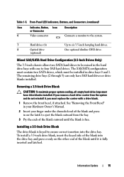
... connector Connects a monitor to the system. 7 Hard drives (6) 8 Optical drive (optional) Up to four SAS hard drives. The remaining drive bays (2 through 5) can only have drive blanks installed. If you must replace the carrier with one to six 3.5-inch hot-plug hard drives. Installing a 3.5-Inch Drive Blank The drive blank is free. To install a 3.5-inch drive blank, insert the keyed side of the...
... connector Connects a monitor to the system. 7 Hard drives (6) 8 Optical drive (optional) Up to four SAS hard drives. The remaining drive bays (2 through 5) can only have drive blanks installed. If you must replace the carrier with one to six 3.5-inch hot-plug hard drives. Installing a 3.5-Inch Drive Blank The drive blank is free. To install a 3.5-inch drive blank, insert the keyed side of the...
Information Update
Page 17
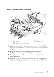
... connector. 5 Disconnect the SAS cable(s) from the back of the SAS cable connectors. 6 If an optical drive is installed, disconnect the data cable from the backplane connectors. See Figure 1-4 for the location of the optical drive. 7 If present, remove the storage controller daughter card. Figure 1-3. See "Removing a SAS Controller Daughter Card" in your Hardware Owner...
... connector. 5 Disconnect the SAS cable(s) from the back of the SAS cable connectors. 6 If an optical drive is installed, disconnect the data cable from the backplane connectors. See Figure 1-4 for the location of the optical drive. 7 If present, remove the storage controller daughter card. Figure 1-3. See "Removing a SAS Controller Daughter Card" in your Hardware Owner...
Information Update
Page 18
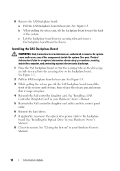
...of the system until it snaps into the securing slots on the drive cage are authorized to the backplane board. See your Hardware Owner's Manual. 8 Close the system. See "Installing the Optical Drive" in your Hardware Owner's Manual. 5 Reattach the SAS controller daughter... card cables and the control panel cable. 6 Reinsert the hard drives. 7 If applicable, reconnect the optical drive power cable to remove the system cover and access...
...of the system until it snaps into the securing slots on the drive cage are authorized to the backplane board. See your Hardware Owner's Manual. 8 Close the system. See "Installing the Optical Drive" in your Hardware Owner's Manual. 5 Reattach the SAS controller daughter... card cables and the control panel cable. 6 Reinsert the hard drives. 7 If applicable, reconnect the optical drive power cable to remove the system cover and access...

Hardware Owner's Manual
Page 5
... 77 Expansion-Card Cage 77 Removing the Expansion-Card Cage 77 Replacing the Expansion-Card Cage 79 RAC Card 79 Removing the RAC Card 79 Installing a RAC Card 81 Optical Drive 81 Removing the Optical Drive from the System 82 Installing the Optical Drive 83 Removing the Optical Drive From the Optical Drive Tray 83 Installing an Optical Drive Into the Optical Drive Tray 84 Contents 5
... 77 Expansion-Card Cage 77 Removing the Expansion-Card Cage 77 Replacing the Expansion-Card Cage 79 RAC Card 79 Removing the RAC Card 79 Installing a RAC Card 81 Optical Drive 81 Removing the Optical Drive from the System 82 Installing the Optical Drive 83 Removing the Optical Drive From the Optical Drive Tray 83 Installing an Optical Drive Into the Optical Drive Tray 84 Contents 5
Hardware Owner's Manual
Page 7
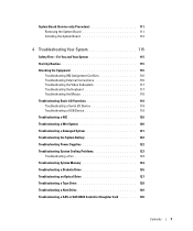
System Board (Service-only Procedure 111 Removing the System Board 111 Installing the System Board 112 4 Troubleshooting Your System 115 Safety First-For You and Your System 115 Start-Up Routine 115 Checking ... System Battery 122 Troubleshooting Power Supplies 122 Troubleshooting System Cooling Problems 123 Troubleshooting a Fan 124 Troubleshooting System Memory 124 Troubleshooting a Diskette Drive 126 Troubleshooting an Optical Drive 127 Troubleshooting a Tape Drive 128 Troubleshooting a Hard Drive 129 Troubleshooting a SAS or SAS RAID Controller Daughter Card 130 Contents 7
System Board (Service-only Procedure 111 Removing the System Board 111 Installing the System Board 112 4 Troubleshooting Your System 115 Safety First-For You and Your System 115 Start-Up Routine 115 Checking ... System Battery 122 Troubleshooting Power Supplies 122 Troubleshooting System Cooling Problems 123 Troubleshooting a Fan 124 Troubleshooting System Memory 124 Troubleshooting a Diskette Drive 126 Troubleshooting an Optical Drive 127 Troubleshooting a Tape Drive 128 Troubleshooting a Hard Drive 129 Troubleshooting a SAS or SAS RAID Controller Daughter Card 130 Contents 7
Hardware Owner's Manual
Page 31
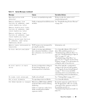
See "Using the System Setup Program" on page 132. Cables to install PCIe device BIOS (Option ROM) checksum failure detected during shadowing. If the problem persists, see "Troubleshooting a Diskette Drive" on page 126, "Troubleshooting an Optical Drive" on page 127, and "Troubleshooting a Hard Drive" on setting the order of manufacturing mode. About Your System 31 Use...
See "Using the System Setup Program" on page 132. Cables to install PCIe device BIOS (Option ROM) checksum failure detected during shadowing. If the problem persists, see "Troubleshooting a Diskette Drive" on page 126, "Troubleshooting an Optical Drive" on page 127, and "Troubleshooting a Hard Drive" on setting the order of manufacturing mode. About Your System 31 Use...
Hardware Owner's Manual
Page 35
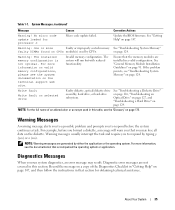
See "Getting Help" on page 91. See "General Memory Module Installation Guidelines" on page 147. See "Troubleshooting a Diskette Drive" on page 126, "Troubleshooting an Optical Drive" on page 127, and "Troubleshooting a Hard Drive" on page 124. Warning Messages A warning message alerts you to a possible problem and prompts you may result. For more information, see "Troubleshooting System...
See "Getting Help" on page 91. See "General Memory Module Installation Guidelines" on page 147. See "Troubleshooting a Diskette Drive" on page 126, "Troubleshooting an Optical Drive" on page 127, and "Troubleshooting a Hard Drive" on page 124. Warning Messages A warning message alerts you to a possible problem and prompts you may result. For more information, see "Troubleshooting System...
Hardware Owner's Manual
Page 52
...14 13 1 RAID battery (optional) 2 4 power supply bay 5 7 power supplies (1 or 2) 8 10 heatsinks and 11 microprocessors (1 or 2) 13 slimline optical drive (optional) 14 16 control panel SAS controller or optional SAS 3 RAID controller daughter card cooling shroud 6 center riser (PCIe slot 1) 9 hot-pluggable fans (4) 12...In Figure 3-1, the bezel and system cover are authorized to 8) 52 Installing System Components Figure 3-1. See your Product Information Guide for optional diskette 15 drive and/or tape drive sideplane expansion-card cage and left riser (PCIe slots 2 and 3)...
...14 13 1 RAID battery (optional) 2 4 power supply bay 5 7 power supplies (1 or 2) 8 10 heatsinks and 11 microprocessors (1 or 2) 13 slimline optical drive (optional) 14 16 control panel SAS controller or optional SAS 3 RAID controller daughter card cooling shroud 6 center riser (PCIe slot 1) 9 hot-pluggable fans (4) 12...In Figure 3-1, the bezel and system cover are authorized to 8) 52 Installing System Components Figure 3-1. See your Product Information Guide for optional diskette 15 drive and/or tape drive sideplane expansion-card cage and left riser (PCIe slots 2 and 3)...
Hardware Owner's Manual
Page 53
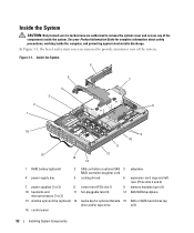
.... An optional 3.5-inch diskette drive and an optional tape drive are installed directly on page 139. For more information, see "Optical Drive" on page 65. See Figure 3-2. The hard drives connect to the power button, diskette drive, optical drive, and hard drive(s). During an installation or troubleshooting procedure, you may...media bay. Several hardware options, such as the microprocessors and memory, are also available for an optional optical drive. Installing System Components 53 For more information, see "System Board Jumpers" on the system board. A control panel...
.... An optional 3.5-inch diskette drive and an optional tape drive are installed directly on page 139. For more information, see "Optical Drive" on page 65. See Figure 3-2. The hard drives connect to the power button, diskette drive, optical drive, and hard drive(s). During an installation or troubleshooting procedure, you may...media bay. Several hardware options, such as the microprocessors and memory, are also available for an optional optical drive. Installing System Components 53 For more information, see "System Board Jumpers" on the system board. A control panel...
Hardware Owner's Manual
Page 70
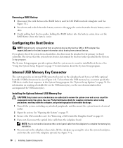
...to disconnect the control panel cable from its electrical outlet. 2 Open the system. See support.dell.com for information about the System Setup program. To boot from external devices. Installing the Optional Internal USB Memory Key CAUTION: Only trained service technicians are authorized to remove the..., draw out the RAID battery from an external device attached to the left on page 68. 4 If present, disconnect the optical drive cable from a hard drive, the drive must specify the USB device in the boot sequence in the System Setup program. See Figure 3-12. 2 Press down and ...
...to disconnect the control panel cable from its electrical outlet. 2 Open the system. See support.dell.com for information about the System Setup program. To boot from external devices. Installing the Optional Internal USB Memory Key CAUTION: Only trained service technicians are authorized to remove the..., draw out the RAID battery from an external device attached to the left on page 68. 4 If present, disconnect the optical drive cable from a hard drive, the drive must specify the USB device in the boot sequence in the System Setup program. See Figure 3-12. 2 Press down and ...

Hardware Owner's Manual
Page 185
mouse troubleshooting, 118 N NIC connectors, 17 indicators, 19 troubleshooting, 120 NIC TOE, 96 O optical drive installing, 83 installing into tray, 84 removing, 82 removing from tray, 83 troubleshooting, 127 P password disabling, 145 setup, 48 system, 46 PCIe expansion cards installation guidelines, 72 installing, 72 removing, 74 PCIe expansion cards (continued) riser boards, 144 troubleshooting, 132 PCIe expansion...
mouse troubleshooting, 118 N NIC connectors, 17 indicators, 19 troubleshooting, 120 NIC TOE, 96 O optical drive installing, 83 installing into tray, 84 removing, 82 removing from tray, 83 troubleshooting, 127 P password disabling, 145 setup, 48 system, 46 PCIe expansion cards installation guidelines, 72 installing, 72 removing, 74 PCIe expansion cards (continued) riser boards, 144 troubleshooting, 132 PCIe expansion...


