Dell PowerEdge 2970 Support Question
Dell PowerEdge 2970 Support Question
Find answers below for this question about Dell PowerEdge 2970.Need a Dell PowerEdge 2970 manual? We have 7 online manuals for this item!
Question posted by fragml on September 6th, 2014
How To Install Memory In Poweredge 2970
The person who posted this question about this Dell product did not include a detailed explanation. Please use the "Request More Information" button to the right if more details would help you to answer this question.
Current Answers
Related Dell PowerEdge 2970 Manual Pages
Installing a SATA Optical Drive - Page 1
Dell™ PowerEdge™ 19x0 and 29x0 Systems
Installing a SATA Optical Drive
Installing a SATA Optical Drive - Page 3

... Drive - c Release the spring latch at the back of the tray and slide the drive tray out of the optical drive.
6 PowerEdge 2900 and 1900 systems only: Perform the following steps.
Installing a SATA Optical Drive
3 WARNING: Only trained service technicians are authorized to which a SATA optical drive is being added, or in...
Installing a SATA Optical Drive - Page 4
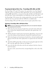
Preparing the Optical Drive Tray - PowerEdge 2970, 2950, and 1950
For PowerEdge 2970 and 2950 systems, the optical drive tray that shipped with the SATA drive installation kit.
See Figure 1-1.
5 Lower the left side of the optical drive to lock it into the corresponding holes in the same carrier. If you must ...
Installing a SATA Optical Drive - Page 5

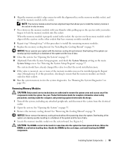
Figure 1-1.
Replacing the Optical Drive in a PowerEdge 2950 or 2970 System
2 1
3
4
5
6
7
1 optical drive 3 interposer 5 SATA power cable 7 optical drive carrier
2 interposer release latch 4 SATA cable 6 carrier latch
Replacing a PowerEdge 1950 Optical Drive
NOTE: The replacement drive tray provided in the installation kit must be used with the holes in the side of the drive. See...
Installing a SATA Optical Drive - Page 6

...the branching power cable) to the back of the chipset shroud. See Figure 1-3. Figure 1-2. Installing a SATA Optical Drive in the fan bracket and follow the power cable routing to the SATA_A ...Connect the branching power cable to the SATA_A connector on the system board.
6
Installing a SATA Optical Drive
PowerEdge 1950
1 Insert the optical drive tray into the system until it is fully ...
Installing a SATA Optical Drive - Page 7

...
2 SATA_A connector on the system and attached peripherals.
Installing the SATA Optical Drive - Installing a SATA Optical Drive
7
See "Closing the System" in your Hardware Owner's Manual.
6 Close the system. SATA Cable Routing in your Hardware Owner's Manual.
7 Reconnect the system to the power supply connector. PowerEdge 2970 or 2950
1 Insert the optical drive tray...
Installing a SATA Optical Drive - Page 8

... of the system until the bracket detaches from the chassis slots.
6 Route the SATA cable in the cable channel in the PowerEdge 2950 and 2970
1
2
3 4 5
1 SATA_B connector on the system board.
SATA Cable Routing in the right wall of the cable ... system board 2 cable retention bracket
3 SATA data cable
4 SATA power cable
5 optical drive
8
Installing a SATA Optical Drive Figure 1-4.
Installing a SATA Optical Drive - Page 9

... back of the fan bracket and connect the cable to power and turn on the system and attached peripherals. PowerEdge 2900 and 1900
1 If the mounting screws are not attached to the drive, install them now.
2 Align the mounting screws with the bay slide slots and insert the optical drive into the...
Information Update - Page 5
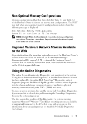
... Administrator Diagnostics tool mentioned in the section "Using Server Administration Diagnostics" in the Hardware Owner's Manual has been replaced by the online Dell PowerEdge™ Diagnostics suite of different speeds renders the memory configuration non-optimal. Non-Optimal Memory Configurations
Memory configurations other than those listed in Table 3-1 and Table 3-2 of the Hardware...
Hardware Owner's Manual - Page 6

...Drive 87 Removing and Replacing the Tape Drive Cable Retention Bracket . . . . 89
System Memory 91 General Memory Module Installation Guidelines 91 Memory Sparing Support 92 Installing Memory Modules 94 Removing Memory Modules 95
Integrated NIC TOE 96
Processors 96 Removing a Processor 96 Installing a Processor 98
System Battery 100 Replacing the System Battery 100
Expansion-Card Riser...
Hardware Owner's Manual - Page 25
... Cable B
SAS cable B is configured, but is missing or disconnected.
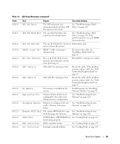
CMOS RAM not See "Getting Help" on . Int Controller Interrupt controller failure. See "Installing Memory Modules" on page 124. Mem Config Err
Memory detected, but not usable. Memory" on page 94.
HDD ## Removed
The specified hard drive has been Information only. See "Troubleshooting System...
Hardware Owner's Manual - Page 29
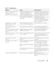
.... Microprocessors with different cache sizes are properly installed. Decreasing available memory
Faulty or improperly installed memory See "Troubleshooting System Memory"
modules. Check other system
example, a failed DIMM) so that node messages for additional information for jumper location.
on page 91. Memory Module Installation
Guidelines" on page 124.
See "Using the...
Hardware Owner's Manual - Page 31
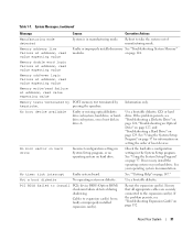
... 126, "Troubleshooting an Optical Drive" on page 127, and "Troubleshooting a Hard Drive" on your operating system documentation. Memory address line failure at address, read value expecting value
Faulty or improperly installed memory See "Troubleshooting System Memory"
modules. No timer tick interrupt Faulty system board.
Reboot to expansion card(s) loose; See "Using the System...
Hardware Owner's Manual - Page 35
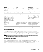
... the Diagnostics Checklist in "Getting Help" on the diskette.
Warning: The installed memory configuration is not optimal. For more information, see the system documentation on..." on the technical support web site. Ensure that you may result. See "General Memory Module Installation Guidelines" on selected drive
Faulty diskette, optical/diskette drive assembly, hard drive, or ...
Hardware Owner's Manual - Page 94

... cooling shroud. CAUTION: The DIMMs are authorized to cool before handling them.
Installing and Removing a Memory Module
1
2 4
3
1 memory module 4 alignment keys (2)
2 memory module socket ejectors (2)
3 socket
94
Installing System Components Installing Memory Modules
CAUTION: Only trained service technicians are hot to be inserted into the socket. See your Product Information...
Hardware Owner's Manual - Page 95
...pulling up on the ejectors with your index fingers to reflect the newly installed memory.
12 If the value is properly seated in the socket.
NOTICE: ...on page 75.
See "Running the System Diagnostics" on the main
System Setup screen.
Installing System Components
95 Removing Memory Modules
CAUTION: Only trained service technicians are hot to remove the system cover and access ...
Hardware Owner's Manual - Page 113

... Replace the center riser board. See "Replacing the Expansion-Card Cage" on page 56. See "Installing the Center Riser Board" on page 94. 8 If applicable, replace the RAC card. See "Installing Memory Modules" on page 104. 14 Replace the power supplies. See "Installing the Cooling Shroud" on page 72. 16 Close the system.
See...
Hardware Owner's Manual - Page 125
See "Using Server Administrator Diagnostics" on page 55. 7 Check the memory banks and ensure that indicates a nonspecific memory problem, continue to the next step.
4 Enter the System Setup program and check the system memory setting. See "Opening the System" on page 135. See "Installing Memory Modules" on the screen.
If the problem is not resolved or if...
Hardware Owner's Manual - Page 126
See "Installing Memory Modules" on page 135. 4 Turn off the system and attached peripherals, and disconnect the system from the electrical outlet. 5 Open the system. Troubleshooting a Diskette Drive
Problem • Error message indicates a diskette drive problem.
See "Using Server Administrator Diagnostics" on page 94.
15 Close the system. See "Opening and Closing the System...
Hardware Owner's Manual - Page 184
..., 79
F
fan bracket removing, 76 replacing, 77
front-panel features, 13
G
guidelines connecting external devices, 17 installing memory, 91 installing PCIe expansion cards, 72
H
hard drive configuring the boot device, 70 drive carrier, 59 indicator codes, 15 installing, 58 removing, 57 troubleshooting, 129
heat sink, 97
hot-plug cooling fans, 63 hard drives, 56...
Similar Questions


How Do I Find If I Have A Drac Card In Poweredge 2970
(Posted by jiWen 10 years ago)
Video On How To Install Dell Poweredge R310 In A Server
(Posted by foria 10 years ago)