
Information Update
Page 16
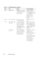
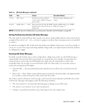
...See "Expansion Card Risers" in the Hardware Owner's Manual. 16 Information Update See "Getting Help" in the Hardware Owner's Manual. Corrective Actions Reseat the RAID battery connector. If the problem persists, see "Troubleshooting System Cooling Problems" in the Hardware Owner's Manual. Table 1-2. Reinstall the expansioncard riser. If the ...to thermal issues. E1625 E1711 PS AC Current PCI PERR B## D## F## PCI PERR Slot # Power source is out of acceptable range. See the "RAID Battery" and see "Troubleshooting an Expansion Card" in the Hardware Owner's Manual.
...See "Expansion Card Risers" in the Hardware Owner's Manual. 16 Information Update See "Getting Help" in the Hardware Owner's Manual. Corrective Actions Reseat the RAID battery connector. If the problem persists, see "Troubleshooting System Cooling Problems" in the Hardware Owner's Manual. Table 1-2. Reinstall the expansioncard riser. If the ...to thermal issues. E1625 E1711 PS AC Current PCI PERR B## D## F## PCI PERR Slot # Power source is out of acceptable range. See the "RAID Battery" and see "Troubleshooting an Expansion Card" in the Hardware Owner's Manual.
Getting Started Guide
Page 6
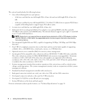
...8226; Front-panel 1x5 LCD for remote systems management. • An integrated VGA-compatible video subsystem with 256 MB of cache memory and a RAID battery. This video subsystem contains 16 MB of the following left riser card that monitors operation of supporting a diskette drive, a CD-ROM ...RAC) for system ID and error messaging. • System ID button on page 10. 4 Getting Started With Your System See support.dell.com for the latest support information about specific features, see "Technical Specifications" on the front and back panels. The systems management circuitry...
...8226; Front-panel 1x5 LCD for remote systems management. • An integrated VGA-compatible video subsystem with 256 MB of cache memory and a RAID battery. This video subsystem contains 16 MB of the following left riser card that monitors operation of supporting a diskette drive, a CD-ROM ...RAC) for system ID and error messaging. • System ID button on page 10. 4 Getting Started With Your System See support.dell.com for the latest support information about specific features, see "Technical Specifications" on the front and back panels. The systems management circuitry...

Getting Started Guide
Page 13
... the entire system ambient operating range, the inrush current may reach 55 A per power supply) Wattage Voltage Heat dissipation Maximum inrush current Batteries System battery RAID battery (optional) one optional internal half height tape backup device external optional USB Two RJ-45 (for 10 ms or less. CR 2032 3.0-V lithium ion...
... the entire system ambient operating range, the inrush current may reach 55 A per power supply) Wattage Voltage Heat dissipation Maximum inrush current Batteries System battery RAID battery (optional) one optional internal half height tape backup device external optional USB Two RJ-45 (for 10 ms or less. CR 2032 3.0-V lithium ion...
Hardware Owner's Manual (PDF)
Page 5
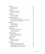
... Bracket 69 SAS Controller Daughter Card 69 Installing a SAS Controller Daughter Card 70 SAS and SAS RAID Controller Daughter Card Cabling Guidelines . . . . . 72 Removing a SAS Controller Daughter Card 74 RAID Battery 74 Installing a RAID Battery 74 Removing a RAID Battery 75 Configuring the Boot Device 76 Expansion Cards 76 Expansion Card Installation Guidelines 76 Installing...
... Bracket 69 SAS Controller Daughter Card 69 Installing a SAS Controller Daughter Card 70 SAS and SAS RAID Controller Daughter Card Cabling Guidelines . . . . . 72 Removing a SAS Controller Daughter Card 74 RAID Battery 74 Installing a RAID Battery 74 Removing a RAID Battery 75 Configuring the Boot Device 76 Expansion Cards 76 Expansion Card Installation Guidelines 76 Installing...
Hardware Owner's Manual (PDF)
Page 7
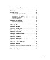
... 120 Troubleshooting a Diskette Drive 121 Troubleshooting an Optical Drive 123 Troubleshooting an External SCSI Tape Drive 123 Troubleshooting a Hard Drive 124 Troubleshooting a SAS or SAS RAID Controller Daughter Card 126 Troubleshooting Expansion Cards 127 Troubleshooting the Microprocessors 128 Contents 7
... 120 Troubleshooting a Diskette Drive 121 Troubleshooting an Optical Drive 123 Troubleshooting an External SCSI Tape Drive 123 Troubleshooting a Hard Drive 124 Troubleshooting a SAS or SAS RAID Controller Daughter Card 126 Troubleshooting Expansion Cards 127 Troubleshooting the Microprocessors 128 Contents 7
Hardware Owner's Manual (PDF)
Page 12
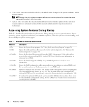
... or technicians. Accessing System Features During Startup Table 1-1 describes keystrokes that may be entered during startup to configure an optional RAID card. See "Running the System Diagnostics" on page 131 Enters the Baseboard Management Controller (BMC) Management Utility, which allows... for your operating system begins to load before you have the optional Dell Remote Access Controller (DRAC), this keystroke allows access to the system event log (SEL). Table 1-1. Enters the RAID configuration utility, which allows access to selected DRAC configuration settings. For more...
... or technicians. Accessing System Features During Startup Table 1-1 describes keystrokes that may be entered during startup to configure an optional RAID card. See "Running the System Diagnostics" on page 131 Enters the Baseboard Management Controller (BMC) Management Utility, which allows... for your operating system begins to load before you have the optional Dell Remote Access Controller (DRAC), this keystroke allows access to the system event log (SEL). Table 1-1. Enters the RAID configuration utility, which allows access to selected DRAC configuration settings. For more...
Hardware Owner's Manual (PDF)
Page 15
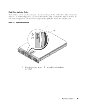
Figure 1-2. Hard-Drive Indicators 1 2 1 drive-status indicator (green 2 green drive-activity indicator and amber) About Your System 15 In RAID configurations, the drive-status indicator lights to indicate the status of the drive. Hard-Drive Indicator Codes The hard-drive carriers have two indicators-the drive-activity indicator and the drive-status indicator. In non-RAID configurations, only the drive-activity indicator lights; the drive-status indicator is off. See Figure 1-2.
Figure 1-2. Hard-Drive Indicators 1 2 1 drive-status indicator (green 2 green drive-activity indicator and amber) About Your System 15 In RAID configurations, the drive-status indicator lights to indicate the status of the drive. Hard-Drive Indicator Codes The hard-drive carriers have two indicators-the drive-activity indicator and the drive-status indicator. In non-RAID configurations, only the drive-activity indicator lights; the drive-status indicator is off. See Figure 1-2.

Hardware Owner's Manual (PDF)
Page 16
NOTE: For non-RAID configurations, only the drive-activity indicator is off six seconds. 16 About Your System Blinks amber four times per second Off Blinks green, amber, and ... green. After the drive is installed, the "drive being prepared for insertion or removal" pattern. Hard-Drive Indicator Patterns for RAID Condition Identify drive/preparing for removal Drive ready for RAID hard drives. The drive-status indicator is active. Table 1-3 lists the drive indicator patterns for insertion or removal Drive predicted failure...
NOTE: For non-RAID configurations, only the drive-activity indicator is off six seconds. 16 About Your System Blinks amber four times per second Off Blinks green, amber, and ... green. After the drive is installed, the "drive being prepared for insertion or removal" pattern. Hard-Drive Indicator Patterns for RAID Condition Identify drive/preparing for removal Drive ready for RAID hard drives. The drive-status indicator is active. Table 1-3 lists the drive indicator patterns for insertion or removal Drive predicted failure...
Hardware Owner's Manual (PDF)
Page 20
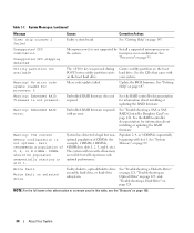
... page 119. Memory has exceeded acceptable See "Troubleshooting System temperature and has been Cooling Problems" on page 119. disabled to prevent damage to connector. See "RAID Battery" on page 147. Table 1-6. See "Getting Help" on thermal issues. Cooling Problems" on page 147. See "Getting Help" on page 119. ...acceptable range. page 74, and "Troubleshooting System Cooling Problems" on page 118. "Troubleshooting System Cooling heating. The system is either missing, Reseat the RAID battery bad, or unable to recharge due to the components. Setup program...
... page 119. Memory has exceeded acceptable See "Troubleshooting System temperature and has been Cooling Problems" on page 119. disabled to prevent damage to connector. See "RAID Battery" on page 147. Table 1-6. See "Getting Help" on thermal issues. Cooling Problems" on page 147. See "Getting Help" on page 119. ...acceptable range. page 74, and "Troubleshooting System Cooling Problems" on page 118. "Troubleshooting System Cooling heating. The system is either missing, Reseat the RAID battery bad, or unable to recharge due to the components. Setup program...
Hardware Owner's Manual (PDF)
Page 24
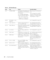
... powering on. some invalid configurations may prevent the system from powering on page 90. See "Installing Memory Modules" on . If the problem persists, see your RAID documentation. See "SAS Controller Daughter Card" on page 124. If problem persists, replace cable. DMA Controller DMA controller failure. See "Troubleshooting a Hard Drive" on page...
... powering on. some invalid configurations may prevent the system from powering on page 90. See "Installing Memory Modules" on . If the problem persists, see your RAID documentation. See "SAS Controller Daughter Card" on page 124. If problem persists, replace cable. DMA Controller DMA controller failure. See "Troubleshooting a Hard Drive" on page...
Hardware Owner's Manual (PDF)
Page 27
...returns to remove the message from the display: • Clear the SEL - You can often specify a very precise fault condition that the RAID Replace RAID battery. Turn off the system and disconnect it from the LCD. charge left. For example, if the code E1418 CPU_1_Presence appears, you receive...Event Log is easily corrected. W1228 ROMB Batt < 24hr Warns predictively that is full of an abbreviation or acronym used in socket 1. See "RAID battery has less than 24 hours of range, the LCD displays the fault; For example, if temperature for the system. • Power ...
...returns to remove the message from the display: • Clear the SEL - You can often specify a very precise fault condition that the RAID Replace RAID battery. Turn off the system and disconnect it from the LCD. charge left. For example, if the code E1418 CPU_1_Presence appears, you receive...Event Log is easily corrected. W1228 ROMB Batt < 24hr Warns predictively that is full of an abbreviation or acronym used in socket 1. See "RAID battery has less than 24 hours of range, the LCD displays the fault; For example, if temperature for the system. • Power ...
Hardware Owner's Manual (PDF)
Page 34
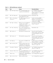
...accessible but nonoptimal population of DIMMs (for information about installing or updating the RAID firmware. Warning! See the RAID controller documentation for example, 1 DIMM, 6 DIMMs, 4 DIMMs in slots 1, 2, 5, and 6, etc.). Dell recommends a population of an abbreviation or acronym used in slot 1. Table ...Utility partition not available The key was pressed during POST, but no utility partition exists on page 93. Warning: Embedded RAID error. Warning: The current memory configuration is not optimal. System has detected a legal but will run with your system...
...accessible but nonoptimal population of DIMMs (for information about installing or updating the RAID firmware. Warning! See the RAID controller documentation for example, 1 DIMM, 6 DIMMs, 4 DIMMs in slots 1, 2, 5, and 6, etc.). Dell recommends a population of an abbreviation or acronym used in slot 1. Table ...Utility partition not available The key was pressed during POST, but no utility partition exists on page 93. Warning: Embedded RAID error. Warning: The current memory configuration is not optimal. System has detected a legal but will run with your system...

Hardware Owner's Manual (PDF)
Page 51
... the following system components: • Hard drives • Power supplies • System fans • Cooling shroud • Fan brackets • SAS controller daughter card • RAID battery • Expansion cards • Expansion card cage • RAC card • Optical, diskette, and tape drives • System memory • Processors • System battery...
... the following system components: • Hard drives • Power supplies • System fans • Cooling shroud • Fan brackets • SAS controller daughter card • RAID battery • Expansion cards • Expansion card cage • RAC card • Optical, diskette, and tape drives • System memory • Processors • System battery...
Hardware Owner's Manual (PDF)
Page 52
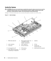
... authorized to remove the system cover and access any of the system. Inside the System 4 5 3 6 2 1 14 13 9 10 11 12 7 8 1 RAID battery (optional) 2 SAS controller daughter card 3 sideplane or SAS RAID controller daughter card (optional) 4 power supply bay 5 power supplies (2) 6 left riser 7 central riser 8 memory modules (8) 9 heatsinks and microprocessors (2) 10 hot-pluggable...
... authorized to remove the system cover and access any of the system. Inside the System 4 5 3 6 2 1 14 13 9 10 11 12 7 8 1 RAID battery (optional) 2 SAS controller daughter card 3 sideplane or SAS RAID controller daughter card (optional) 4 power supply bay 5 power supplies (2) 6 left riser 7 central riser 8 memory modules (8) 9 heatsinks and microprocessors (2) 10 hot-pluggable...
Hardware Owner's Manual (PDF)
Page 53
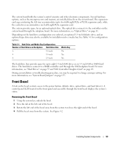
... Bezel 1 Using the system key, unlock the bezel. 2 Press the tab at the left end of the bezel. 3 Rotate the left riser accommodates up to a RAID controller card through the sideplane board. The optical drive connects to release the right end of the bezel away from the system. For more information...
... Bezel 1 Using the system key, unlock the bezel. 2 Press the tab at the left end of the bezel. 3 Rotate the left riser accommodates up to a RAID controller card through the sideplane board. The optical drive connects to release the right end of the bezel away from the system. For more information...
Hardware Owner's Manual (PDF)
Page 56
... to partition and format SAS or SATA hard drives. You may need to ensure that have drive blanks installed. The process for the optional SAS RAID controller daughter card to use different programs than those provided with a universal interposer card. See "Removing the Front Bezel" on the latch to remove or...
... to partition and format SAS or SATA hard drives. You may need to ensure that have drive blanks installed. The process for the optional SAS RAID controller daughter card to use different programs than those provided with a universal interposer card. See "Removing the Front Bezel" on the latch to remove or...
Hardware Owner's Manual (PDF)
Page 57
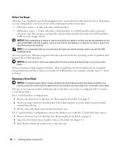
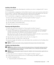
...the drive is fully seated. 4 Close the handle to release the drive. See "Removing the Front Bezel" on page 53. 2 From the RAID management software, prepare the drive for removal. 3 Open the drive carrier release handle to lock the blank in place. 5 Replace the front bezel... to a partially installed carrier can be removed safely. Installing a Drive Blank The process for installing a drive blank depends on whether your SAS RAID controller documentation for information about hot-plug drive removal. Installing a Hot-Plug Hard Drive NOTICE: When installing a hard drive, ensure that the ...
...the drive is fully seated. 4 Close the handle to release the drive. See "Removing the Front Bezel" on page 53. 2 From the RAID management software, prepare the drive for removal. 3 Open the drive carrier release handle to lock the blank in place. 5 Replace the front bezel... to a partially installed carrier can be removed safely. Installing a Drive Blank The process for installing a drive blank depends on whether your SAS RAID controller documentation for information about hot-plug drive removal. Installing a Hot-Plug Hard Drive NOTICE: When installing a hard drive, ensure that the ...
Hardware Owner's Manual (PDF)
Page 69
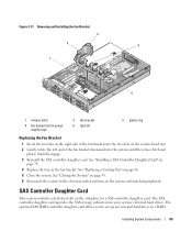
Removing and Installing the Fan Bracket 3 2 4 1 5 1 release latch 4 fan bracket slot in a RAID Installing System Components 69 See "Closing the System" on page 55. 6 Reconnect the system to set up any internal hard drives in power supply cage 2 ... the fan bracket downward into the system until the release latch and plastic clip fully engage. 3 Reinstall the SAS controller daughter card. The optional SAS RAID controller daughter card allows you to the electrical outlet and turn on the sideplane for your system's internal hard drives. The SAS controller daughter card...
Removing and Installing the Fan Bracket 3 2 4 1 5 1 release latch 4 fan bracket slot in a RAID Installing System Components 69 See "Closing the System" on page 55. 6 Reconnect the system to set up any internal hard drives in power supply cage 2 ... the fan bracket downward into the system until the release latch and plastic clip fully engage. 3 Reinstall the SAS controller daughter card. The optional SAS RAID controller daughter card allows you to the electrical outlet and turn on the sideplane for your system's internal hard drives. The SAS controller daughter card...
Hardware Owner's Manual (PDF)
Page 70
...facing the sideplane board. 5 Aligning the chassis slots on the SAS daughter card tray with the mid-section standoff on the RAID card DIMM while installing the RAID card into the sideplane board. configuration. Ensure that the card is different (the SAS controller daughter card has only one connector... not press on the SAS controller daughter card and fully seat the card in Figure 3-12. NOTE: If you are installing a replacement RAID card, do not remove the plastic cover protecting the card until after installation of daughter cards is aligned with the corresponding hooks on the ...
...facing the sideplane board. 5 Aligning the chassis slots on the SAS daughter card tray with the mid-section standoff on the RAID card DIMM while installing the RAID card into the sideplane board. configuration. Ensure that the card is different (the SAS controller daughter card has only one connector... not press on the SAS controller daughter card and fully seat the card in Figure 3-12. NOTE: If you are installing a replacement RAID card, do not remove the plastic cover protecting the card until after installation of daughter cards is aligned with the corresponding hooks on the ...

Hardware Owner's Manual (PDF)
Page 71
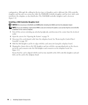
... 2 4 SAS controller daughter card 5 battery connector 7 SAS controller daughter card tray SAS controller daughter card 3 slot SAS connectors 0 and 1 (for 6 RAID card only) out to backplane SAS_A or SAS_B (for RAID card only) connector release tab chassis slots (2) 6 Attach any cables from the SAS controller daughter card to the backplane, referring to...
... 2 4 SAS controller daughter card 5 battery connector 7 SAS controller daughter card tray SAS controller daughter card 3 slot SAS connectors 0 and 1 (for 6 RAID card only) out to backplane SAS_A or SAS_B (for RAID card only) connector release tab chassis slots (2) 6 Attach any cables from the SAS controller daughter card to the backplane, referring to...


