
Information Update
Page 3
Power 2950 II and PowerEdge 2950 III Systems 9 System Board Replacement - New System Features 5 New Performance Features 5 New High-Efficiency Power Supply and Power Monitoring Features 5 New I/O and Storage Features 6 New Security Features 6 Optional Internal USB Memory Key 6 Installing the Optional Internal USB Memory Key 7 Support for 8-GB Memory Modules - PowerEdge 2950 III Systems 9 Processor Upgrades - Safeguarding Encrypted Data 9 System Message Update 10 LCD Status Messages Update 15 Contents 3 Contents Non-Optimal Memory Configurations 5 PowerEdge 2950 III -
Power 2950 II and PowerEdge 2950 III Systems 9 System Board Replacement - New System Features 5 New Performance Features 5 New High-Efficiency Power Supply and Power Monitoring Features 5 New I/O and Storage Features 6 New Security Features 6 Optional Internal USB Memory Key 6 Installing the Optional Internal USB Memory Key 7 Support for 8-GB Memory Modules - PowerEdge 2950 III Systems 9 Processor Upgrades - Safeguarding Encrypted Data 9 System Message Update 10 LCD Status Messages Update 15 Contents 3 Contents Non-Optimal Memory Configurations 5 PowerEdge 2950 III -
Information Update
Page 4
System Setup Program Update 19 Memory Screen 19 CPU Information Screen 20 Integrated Devices Screen 20 System Security Screen 21 Serial Communication Screen 23 Operating System Information 23 Enumeration of NICs 23 RHEL - Incorrect Processor Information 23 System Support for Microsoft Windows 2000 . . . 24 System Diagnostics Update 24 4 Contents
System Setup Program Update 19 Memory Screen 19 CPU Information Screen 20 Integrated Devices Screen 20 System Security Screen 21 Serial Communication Screen 23 Operating System Information 23 Enumeration of NICs 23 RHEL - Incorrect Processor Information 23 System Support for Microsoft Windows 2000 . . . 24 System Diagnostics Update 24 4 Contents
Information Update
Page 5
PowerEdge 2950 III - New High-Efficiency Power Supply and Power Monitoring Features • Higher system efficiency on power conversion across workloads. • Baseboard Management Control (BMC) power monitoring monitors current, voltage, and power utilization in the DIMM set for Setup NOTE: Mixing DIMMs of different speeds renders the memory configuration non-optimal. New System...
PowerEdge 2950 III - New High-Efficiency Power Supply and Power Monitoring Features • Higher system efficiency on power conversion across workloads. • Baseboard Management Control (BMC) power monitoring monitors current, voltage, and power utilization in the DIMM set for Setup NOTE: Mixing DIMMs of different speeds renders the memory configuration non-optimal. New System...

Information Update
Page 6
... documentation that contain multiple LUNs (Logical Unit Numbers) must be formatted using the format utility provided by the key manufacturer. The USB memory key can be enabled in the Integrated Devices screen of supporting 10-Mbps, 100-Mbps, and 1000-Mbps data rates, and iSCSI remote... x 23.2mm width (0.91") x 67mm length (2.64"). 6 Information Update CAUTION: To avoid interference with a boot image and then specify the USB memory key in the boot sequence in the Hardware Owner's Manual. New I/O and Storage Features • Optional Intel quad-port Gigabit Ethernet NIC, capable of ...
... documentation that contain multiple LUNs (Logical Unit Numbers) must be formatted using the format utility provided by the key manufacturer. The USB memory key can be enabled in the Integrated Devices screen of supporting 10-Mbps, 100-Mbps, and 1000-Mbps data rates, and iSCSI remote... x 23.2mm width (0.91") x 67mm length (2.64"). 6 Information Update CAUTION: To avoid interference with a boot image and then specify the USB memory key in the boot sequence in the Hardware Owner's Manual. New I/O and Storage Features • Optional Intel quad-port Gigabit Ethernet NIC, capable of ...
Information Update
Page 7
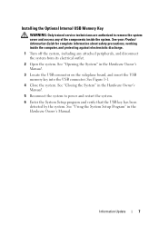
... System Setup Program" in the Hardware Owner's Manual. 3 Locate the USB connector on the sideplane board, and insert the USB memory key into the USB connector. Installing the Optional Internal USB Memory Key WARNING: Only trained service technicians are authorized to power and restart the system. 6 Enter the System Setup program and...
... System Setup Program" in the Hardware Owner's Manual. 3 Locate the USB connector on the sideplane board, and insert the USB memory key into the USB connector. Installing the Optional Internal USB Memory Key WARNING: Only trained service technicians are authorized to power and restart the system. 6 Enter the System Setup program and...
Information Update
Page 8
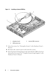
See "Using the System Setup Program" in the Hardware Owner's Manual. 8 Reconnect the system to power and restart the system. 9 Enter the System Setup program and verify that the USB key has been detected by the system. Figure 1-1. Installing an Internal USB Key 3 2 1 1 sideplane board 3 USB memory key 2 internal USB connector 7 Close the system. See "Closing the System" in the Hardware Owner's Manual. 8 Information Update
See "Using the System Setup Program" in the Hardware Owner's Manual. 8 Reconnect the system to power and restart the system. 9 Enter the System Setup program and verify that the USB key has been detected by the system. Figure 1-1. Installing an Internal USB Key 3 2 1 1 sideplane board 3 USB memory key 2 internal USB connector 7 Close the system. See "Closing the System" in the Hardware Owner's Manual. 8 Information Update
Information Update
Page 9
PowerEdge 2950 III Systems PowerEdge 2950 III systems have added support for 8-GB Memory Modules - Loading the latest BIOS version ensures that your system. Processor Upgrades - Support for the following approved 8-GB memory configurations: •64 GB - 8 x 8-GB quad-rank memory modules •48 GB - 4 x 8-GB quad-rank and 4 x 4-GB dual-rank memory modules If 64 GB of memory is...
PowerEdge 2950 III Systems PowerEdge 2950 III systems have added support for 8-GB Memory Modules - Loading the latest BIOS version ensures that your system. Processor Upgrades - Support for the following approved 8-GB memory configurations: •64 GB - 8 x 8-GB quad-rank memory modules •48 GB - 4 x 8-GB quad-rank and 4 x 4-GB dual-rank memory modules If 64 GB of memory is...
Information Update
Page 10
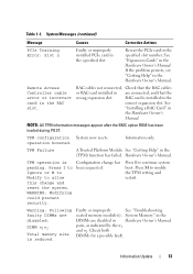
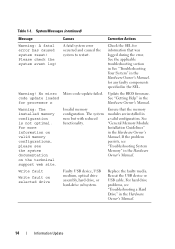
...see "Trouble- supported. See your hard drive(s). System Messages Message Causes Corrective Actions Alert! Node Interleaving disabled! The system For memory configuration runs but with the system. Be sure to create a recovery key during system setup. Table 1-1. System messages appear on ... to store this recovery key. The memory configuration Ensure that the memory does not support node modules are installed in a interleaving, or the configuration that node for additional information interleaving cannot be for the PowerEdge 2950 III system and the probable cause and...
...see "Trouble- supported. See your hard drive(s). System Messages Message Causes Corrective Actions Alert! Node Interleaving disabled! The system For memory configuration runs but with the system. Be sure to create a recovery key during system setup. Table 1-1. System messages appear on ... to store this recovery key. The memory configuration Ensure that the memory does not support node modules are installed in a interleaving, or the configuration that node for additional information interleaving cannot be for the PowerEdge 2950 III system and the probable cause and...
Information Update
Page 13
... Owner's Manual. WARNING: Modifying could prevent security. Press I to Ignore or M to Modify to allow this change has been requested. System Memory" in the DIMMs are disabled in the (TPM) function has failed. Check both DIMMs for a possible fault. Configuration change and reset the ...continued) Message Causes Corrective Actions PCIe Training Error: Slot n Faulty or improperly installed PCIe card in are disabled: DIMM n1 n2 Total memory size is pending. NOTE: All TPM information messages appear after the BMC option ROM has been loaded during POST. Faulty or improperly See...
... Owner's Manual. WARNING: Modifying could prevent security. Press I to Ignore or M to Modify to allow this change has been requested. System Memory" in the DIMMs are disabled in the (TPM) function has failed. Check both DIMMs for a possible fault. Configuration change and reset the ...continued) Message Causes Corrective Actions PCIe Training Error: Slot n Faulty or improperly installed PCIe card in are disabled: DIMM n1 n2 Total memory size is pending. NOTE: All TPM information messages appear after the BMC option ROM has been loaded during POST. Faulty or improperly See...
Information Update
Page 14
... and caused the system to restart. for any faulty components specified in the Hardware Owner's Manual. For more information on valid memory configurations, please see the system documentation on selected drive Faulty USB device, USB medium, optical drive assembly, hard drive, or... the faulty media. System Messages (continued) Message Causes Corrective Actions Warning: A fatal error has caused system reset! Warning: The installed memory configuration is not optimal. Table 1-1. Check the SEL for processor n Hardware Owner's Manual. Update the BIOS firmware. code update loaded See...
... and caused the system to restart. for any faulty components specified in the Hardware Owner's Manual. For more information on valid memory configurations, please see the system documentation on selected drive Faulty USB device, USB medium, optical drive assembly, hard drive, or... the faulty media. System Messages (continued) Message Causes Corrective Actions Warning: A fatal error has caused system reset! Warning: The installed memory configuration is not optimal. Table 1-1. Check the SEL for processor n Hardware Owner's Manual. Update the BIOS firmware. code update loaded See...
Information Update
Page 18
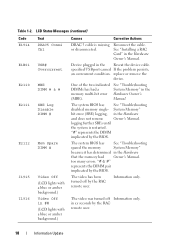
...18 Information Update One of the two indicated See "Troubleshooting DIMMs has had Owner's Manual. The system BIOS has See "Troubleshooting disabled memory single- "# & #" represents the DIMM pair implicated by the BIOS. in the Hardware Owner's Manual. Device plugged in the Hardware...SBE) logging, in the Reseat the device cable. The system BIOS has See "Troubleshooting spared the memory System Memory" because it has determined in the Hardware that the memory had a System Memory" in ## (LCD lights with a blue or amber background.) Causes Corrective Actions DRAC 5 cable...
...18 Information Update One of the two indicated See "Troubleshooting DIMMs has had Owner's Manual. The system BIOS has See "Troubleshooting disabled memory single- "# & #" represents the DIMM pair implicated by the BIOS. in the Hardware Owner's Manual. Device plugged in the Hardware...SBE) logging, in the Reseat the device cable. The system BIOS has See "Troubleshooting spared the memory System Memory" because it has determined in the Hardware that the memory had a System Memory" in ## (LCD lights with a blue or amber background.) Causes Corrective Actions DRAC 5 cable...

Information Update
Page 19
... Node Interleaving field is enabled. Memory Information Screen Options Option System Memory Size System Memory Type System Memory Speed Video Memory System Memory Testing Redundant Memory (Disabled default) Node Interleaving (Disabled default) Low Power Mode (Disabled default) Description Displays the amount of system memory. Displays the type of system memory. Displays the amount of the memory. Information Update 19 Specifies...
... Node Interleaving field is enabled. Memory Information Screen Options Option System Memory Size System Memory Type System Memory Speed Video Memory System Memory Testing Redundant Memory (Disabled default) Node Interleaving (Disabled default) Low Power Mode (Disabled default) Description Displays the amount of system memory. Displays the type of system memory. Displays the amount of the memory. Information Update 19 Specifies...
Information Update
Page 24
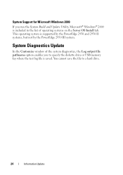
You cannot save the file to specify the diskette drive or USB memory key where the test log file is saved. System Diagnostics Update In the Customize window of operating systems on the Server OS Install tab. System ... diagnostics, the Log output file pathname option enables you run the System Build and Update Utility, Microsoft® Windows® 2000 is supported by the PowerEdge 2950 and 2950 II systems, but not by the...
You cannot save the file to specify the diskette drive or USB memory key where the test log file is saved. System Diagnostics Update In the Customize window of operating systems on the Server OS Install tab. System ... diagnostics, the Log output file pathname option enables you run the System Build and Update Utility, Microsoft® Windows® 2000 is supported by the PowerEdge 2950 and 2950 II systems, but not by the...
Information Update
Page 27
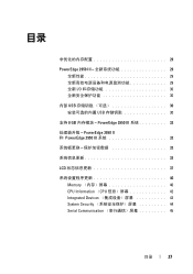
目录 29 PowerEdge 2950 III 29 29 29 全新 I/O 30 30 内部 USB 30 USB 30 支持 8 GB PowerEdge 2950 III 32 PowerEdge 2950 II 和 PowerEdge 2950 III 32 32 33 LCD 37 40 Memory 40 CPU Information (CPU 42 Integrated Devices 42 System Security 44 Serial Communication 45 目录 27
目录 29 PowerEdge 2950 III 29 29 29 全新 I/O 30 30 内部 USB 30 USB 30 支持 8 GB PowerEdge 2950 III 32 PowerEdge 2950 II 和 PowerEdge 2950 III 32 32 33 LCD 37 40 Memory 40 CPU Information (CPU 42 Integrated Devices 42 System Security 44 Serial Communication 45 目录 27
Information Update
Page 29
POST Non-Optimal Memory Configuration Press F1 to continue or F2 for Setup (按 F1 F2 DIMM DIMM PowerEdge 2950 III 全新性能 Intel® Xeon® 5400 系列和 5300 8 GB BMC 信息更新 29
POST Non-Optimal Memory Configuration Press F1 to continue or F2 for Setup (按 F1 F2 DIMM DIMM PowerEdge 2950 III 全新性能 Intel® Xeon® 5400 系列和 5300 8 GB BMC 信息更新 29
Information Update
Page 33
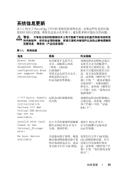
... card found in the Internal_Storage slot! 表 1-1 列出了 PowerEdge 2950 III 表 1-1 信息 原因 纠正措施 Alert! PCIe PCIe SAS No boot device available USB CD USB 程序"。 信息更新 33 Memory configuration does not support Node Interleaving. Node Interleaving disabled! DIMM !!*** Error...
... card found in the Internal_Storage slot! 表 1-1 列出了 PowerEdge 2950 III 表 1-1 信息 原因 纠正措施 Alert! PCIe PCIe SAS No boot device available USB CD USB 程序"。 信息更新 33 Memory configuration does not support Node Interleaving. Node Interleaving disabled! DIMM !!*** Error...

Information Update
Page 36
...; 1-1 信息 原因 纠正措施 Warning: Following faulty DIMMs are disabled: DIMM n1 n2 Total memory size is not optimal. DIMM n1 和 n2 DIMM Warning: A fatal error has caused system reset! Please check the system ...event log! 请查看 SEL SEL Warning! For more information on valid memory configurations, please see the system documentation on the technical support web site. 降低。 Write fault Write fault on selected ...
...; 1-1 信息 原因 纠正措施 Warning: Following faulty DIMMs are disabled: DIMM n1 n2 Total memory size is not optimal. DIMM n1 和 n2 DIMM Warning: A fatal error has caused system reset! Please check the system ...event log! 请查看 SEL SEL Warning! For more information on valid memory configurations, please see the system documentation on the technical support web site. 降低。 Write fault Write fault on selected ...

Information Update
Page 41
表 1-3. Memory Information 选项 System Memory Testing Redundant Memory Disabled Node Interleaving Disabled Low Power Mode Disabled 说明 Enabled Disabled Spare Mode DIMM Node Interleaving Enabled Disabled NUMA Node Interleaving Disabled Disabled Enabled 信息更新 41
表 1-3. Memory Information 选项 System Memory Testing Redundant Memory Disabled Node Interleaving Disabled Low Power Mode Disabled 说明 Enabled Disabled Spare Mode DIMM Node Interleaving Enabled Disabled NUMA Node Interleaving Disabled Disabled Enabled 信息更新 41
Information Update
Page 109
POST Non-Optimal Memory Configuration Press F1 to continue or F2 for Setup F1 F2 DIMM DIMM DIMM PowerEdge 2950 III Intel® Xeon® 5400 5300 2 個。 • 8 GB BMC 109
POST Non-Optimal Memory Configuration Press F1 to continue or F2 for Setup F1 F2 DIMM DIMM DIMM PowerEdge 2950 III Intel® Xeon® 5400 5300 2 個。 • 8 GB BMC 109
Information Update
Page 115
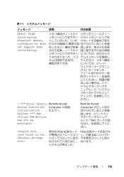
Remote Access Controller RAC Invalid PCIe card found in the Internal_Storage slot! 無効な PCIe PCIe SAS 115 Memory configuration does not support Node Interleaving. れかの DIMM ださい。 !!*** Error: Remote Remote Access Access Controller Controller の初期 initialization ...
Remote Access Controller RAC Invalid PCIe card found in the Internal_Storage slot! 無効な PCIe PCIe SAS 115 Memory configuration does not support Node Interleaving. れかの DIMM ださい。 !!*** Error: Remote Remote Access Access Controller Controller の初期 initialization ...


