
Information Update
Page 3
New System Features 5 New Performance Features 5 New High-Efficiency Power Supply and Power Monitoring Features 5 New I/O and Storage Features 6 New Security Features 6 Optional Internal USB Memory Key 6 Installing the Optional Internal USB Memory Key 7 Support for 8-GB Memory Modules - PowerEdge 2950 III Systems 9 Processor Upgrades - Safeguarding Encrypted Data 9 System Message Update 10 LCD Status Messages Update 15 Contents 3 Contents Non-Optimal Memory Configurations 5 PowerEdge 2950 III - Power 2950 II and PowerEdge 2950 III Systems 9 System Board Replacement -
New System Features 5 New Performance Features 5 New High-Efficiency Power Supply and Power Monitoring Features 5 New I/O and Storage Features 6 New Security Features 6 Optional Internal USB Memory Key 6 Installing the Optional Internal USB Memory Key 7 Support for 8-GB Memory Modules - PowerEdge 2950 III Systems 9 Processor Upgrades - Safeguarding Encrypted Data 9 System Message Update 10 LCD Status Messages Update 15 Contents 3 Contents Non-Optimal Memory Configurations 5 PowerEdge 2950 III - Power 2950 II and PowerEdge 2950 III Systems 9 System Board Replacement -
Information Update
Page 5
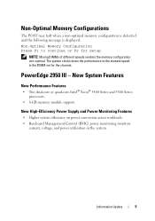
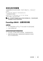
...monitors current, voltage, and power utilization in the DIMM set for Setup NOTE: Mixing DIMMs of different speeds renders the memory configuration non-optimal. The system clocks down the performance to continue or F2 for the channel. New System Features New Performance...; 5400 Series and 5300 Series processors. • 8-GB memory module support. Non-Optimal Memory Configurations The POST may halt when a non-optimal memory configuration is detected and the following message is displayed: Non-Optimal Memory Configuration Press F1 to the slowest speed in the system. PowerEdge 2950 III -
...monitors current, voltage, and power utilization in the DIMM set for Setup NOTE: Mixing DIMMs of different speeds renders the memory configuration non-optimal. The system clocks down the performance to continue or F2 for the channel. New System Features New Performance...; 5400 Series and 5300 Series processors. • 8-GB memory module support. Non-Optimal Memory Configurations The POST may halt when a non-optimal memory configuration is detected and the following message is displayed: Non-Optimal Memory Configuration Press F1 to the slowest speed in the system. PowerEdge 2950 III -
Information Update
Page 9
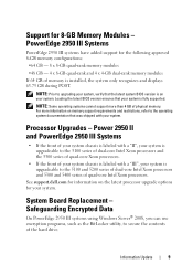
...support.dell.com for your system. Information Update 9 Loading the latest BIOS version ensures that your system. Support for the following approved 8-GB memory configurations: •64 GB - 8 x 8-GB quad-rank memory ...modules •48 GB - 4 x 8-GB quad-rank and 4 x 4-GB dual-rank memory modules If 64 GB of your system chassis is labeled with a "III", your system, verify that was shipped with a "II", your system is upgradeable to secure the contents of physical memory. Power 2950 II and PowerEdge 2950...
...support.dell.com for your system. Information Update 9 Loading the latest BIOS version ensures that your system. Support for the following approved 8-GB memory configurations: •64 GB - 8 x 8-GB quad-rank memory ...modules •48 GB - 4 x 8-GB quad-rank and 4 x 4-GB dual-rank memory modules If 64 GB of your system chassis is labeled with a "III", your system, verify that was shipped with a "II", your system is upgradeable to secure the contents of physical memory. Power 2950 II and PowerEdge 2950...
Information Update
Page 10
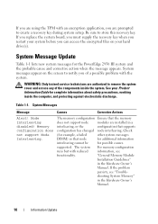
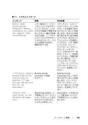
... safety precautions, working inside the system. If the problem persists, see functionality. shooting System Memory" in a interleaving, or the configuration that supports configuration has changed node interleaving. The memory configuration Ensure that node for additional information interleaving cannot be for the PowerEdge 2950 III system and the probable cause and corrective action when the message appears. Table...
... safety precautions, working inside the system. If the problem persists, see functionality. shooting System Memory" in a interleaving, or the configuration that supports configuration has changed node interleaving. The memory configuration Ensure that node for additional information interleaving cannot be for the PowerEdge 2950 III system and the probable cause and corrective action when the message appears. Table...
Information Update
Page 14
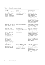
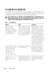
... Owner's Manual. 14 Information Update code update loaded See "Getting Help" in the SEL. Invalid memory configuration. for any faulty components specified in the for information that the memory modules are installed in the Hardware Owner's Manual. Warning! Warning: The installed memory configuration is not optimal. The system runs but with reduced functionality. See "General...
... Owner's Manual. 14 Information Update code update loaded See "Getting Help" in the SEL. Invalid memory configuration. for any faulty components specified in the for information that the memory modules are installed in the Hardware Owner's Manual. Warning! Warning: The installed memory configuration is not optimal. The system runs but with reduced functionality. See "General...

Information Update
Page 19
... default) Description Displays the amount of system memory. When set to Spare Mode, the first rank of memory on the Memory Information screen. Table 1-3. Displays the type of system memory. Specifies whether system memory tests are Enabled and Disabled. When set to Enabled, memory interleaving is supported if a symmetric memory configuration is installed. If this field is set...
... default) Description Displays the amount of system memory. When set to Spare Mode, the first rank of memory on the Memory Information screen. Table 1-3. Displays the type of system memory. Specifies whether system memory tests are Enabled and Disabled. When set to Enabled, memory interleaving is supported if a symmetric memory configuration is installed. If this field is set...
Information Update
Page 29
POST Non-Optimal Memory Configuration Press F1 to continue or F2 for Setup (按 F1 F2 DIMM DIMM PowerEdge 2950 III 全新性能 Intel® Xeon® 5400 系列和 5300 8 GB BMC 信息更新 29
POST Non-Optimal Memory Configuration Press F1 to continue or F2 for Setup (按 F1 F2 DIMM DIMM PowerEdge 2950 III 全新性能 Intel® Xeon® 5400 系列和 5300 8 GB BMC 信息更新 29
Information Update
Page 33
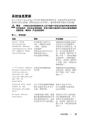
...;序"。 信息更新 33 RAC 卡"。 Invalid PCIe card found in the Internal_Storage slot! Node Interleaving disabled! 表 1-1 列出了 PowerEdge 2950 III 表 1-1 信息 原因 纠正措施 Alert! Memory configuration does not support Node Interleaving.
...;序"。 信息更新 33 RAC 卡"。 Invalid PCIe card found in the Internal_Storage slot! Node Interleaving disabled! 表 1-1 列出了 PowerEdge 2950 III 表 1-1 信息 原因 纠正措施 Alert! Memory configuration does not support Node Interleaving.

Information Update
Page 36
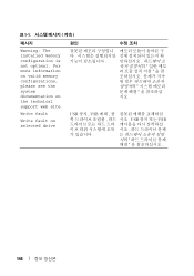
For more information on valid memory configurations, please see the system documentation on the technical support web site. 降低。 Write fault Write fault on ...USB 设备或 USB 36 信息更新 No micro code update loaded for processor n 请更新 BIOS Warning: The installed memory configuration is reduced. Please check the system event log! 请查看 SEL SEL Warning! 表 1-1 信息 原因 纠正&#...
For more information on valid memory configurations, please see the system documentation on the technical support web site. 降低。 Write fault Write fault on ...USB 设备或 USB 36 信息更新 No micro code update loaded for processor n 请更新 BIOS Warning: The installed memory configuration is reduced. Please check the system event log! 请查看 SEL SEL Warning! 表 1-1 信息 原因 纠正&#...
Information Update
Page 109
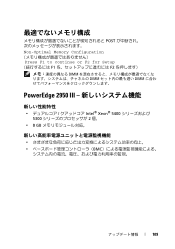
POST Non-Optimal Memory Configuration Press F1 to continue or F2 for Setup F1 F2 DIMM DIMM DIMM PowerEdge 2950 III Intel® Xeon® 5400 5300 2 個。 • 8 GB BMC 109
POST Non-Optimal Memory Configuration Press F1 to continue or F2 for Setup F1 F2 DIMM DIMM DIMM PowerEdge 2950 III Intel® Xeon® 5400 5300 2 個。 • 8 GB BMC 109
Information Update
Page 115
Memory configuration does not support Node Interleaving. れかの DIMM ださい。 !!*** Error: Remote Remote Access Access Controller Controller の初期 initialization failure *** ...
Memory configuration does not support Node Interleaving. れかの DIMM ださい。 !!*** Error: Remote Remote Access Access Controller Controller の初期 initialization failure *** ...

Information Update
Page 120
表 1-1 原因 対応処置 Warning! For more information on valid memory configurations, please see the system documentation on selected drive USB USB USB USB 120 Write fault Write fault on the technical support web site. No micro code update loaded for processor n BIOS ださい。 Warning: The installed memory configuration is not optimal.
表 1-1 原因 対応処置 Warning! For more information on valid memory configurations, please see the system documentation on selected drive USB USB USB USB 120 Write fault Write fault on the technical support web site. No micro code update loaded for processor n BIOS ださい。 Warning: The installed memory configuration is not optimal.

Information Update
Page 137
POST Non-Optimal Memory Configuration Press F1 to continue or F2 for Setup F1 F2 DIMM DIMM PowerEdge 2950 III Intel® Xeon® 5400 5300 • 8GB BMC 137
POST Non-Optimal Memory Configuration Press F1 to continue or F2 for Setup F1 F2 DIMM DIMM PowerEdge 2950 III Intel® Xeon® 5400 5300 • 8GB BMC 137
Information Update
Page 142
Node Interleaving disabled! RAC Invalid PCIe card found in the Internal_Storage slot! 표 1-1 PowerEdge 2950 III 표 1-1 메시지 원인 Alert! PCIe PCIe SAS 142 Memory configuration does not support Node Interleaving. DIMM !!*** Error: Remote Access Controller initialization failure *** RAC virtual USB devices may not be available...
Node Interleaving disabled! RAC Invalid PCIe card found in the Internal_Storage slot! 표 1-1 PowerEdge 2950 III 표 1-1 메시지 원인 Alert! PCIe PCIe SAS 142 Memory configuration does not support Node Interleaving. DIMM !!*** Error: Remote Access Controller initialization failure *** RAC virtual USB devices may not be available...
Information Update
Page 146
Write fault Write fault on the technical support web site. USB 장치 , USB USB USB 146 표 1-1 메시지 Warning: The installed memory configuration is not optimal. For more information on valid memory configurations, please see the system documentation on selected drive 원인 시오 .
Write fault Write fault on the technical support web site. USB 장치 , USB USB USB 146 표 1-1 메시지 Warning: The installed memory configuration is not optimal. For more information on valid memory configurations, please see the system documentation on selected drive 원인 시오 .
Hardware Owner's Manual (PDF)
Page 6
... SCSI Tape Drive 86 Removing and Replacing the Tape Drive Cable Retention Bracket . . . . 88 System Memory 89 General Memory Module Installation Guidelines 89 Non-Optimal Memory Configurations 90 Memory Sparing Support 90 Memory Mirroring Support 90 Installing Memory Modules 90 Removing Memory Modules 92 Activating the Integrated NIC TOE 93 Processors 93 Removing a Processor 93 Installing a Processor 95...
... SCSI Tape Drive 86 Removing and Replacing the Tape Drive Cable Retention Bracket . . . . 88 System Memory 89 General Memory Module Installation Guidelines 89 Non-Optimal Memory Configurations 90 Memory Sparing Support 90 Memory Mirroring Support 90 Installing Memory Modules 90 Removing Memory Modules 92 Activating the Integrated NIC TOE 93 Processors 93 Removing a Processor 93 Installing a Processor 95...
Hardware Owner's Manual (PDF)
Page 24
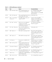
... prevent the system from the system. SAS Cable A SAS cable A is missing or bad. Mem Config Err Memory detected, but is configured, but not usable. Reseat the cable. Error detected during memory configuration. Unusable Memory Memory is not configurable. HDD ## Removed The specified hard drive has been Information only. See "SAS Controller Daughter Card" on page 147...
... prevent the system from the system. SAS Cable A SAS cable A is missing or bad. Mem Config Err Memory detected, but is configured, but not usable. Reseat the cable. Error detected during memory configuration. Unusable Memory Memory is not configurable. HDD ## Removed The specified hard drive has been Information only. See "SAS Controller Daughter Card" on page 147...
Hardware Owner's Manual (PDF)
Page 25
... page 147. Parity Error Parity error. Table 1-6. DRAC Config Dell remote access controller Check screen for specific error messages. MBE Crd # DIMM ## & ## One of the message. If problem persists, see your DRAC documentation. Memory Population Incorrect memory configuration. Prog Timer Programmable interval timer error. See "Getting Help" on page 147. See "Getting Help" on...
... page 147. Parity Error Parity error. Table 1-6. DRAC Config Dell remote access controller Check screen for specific error messages. MBE Crd # DIMM ## & ## One of the message. If problem persists, see your DRAC documentation. Memory Population Incorrect memory configuration. Prog Timer Programmable interval timer error. See "Getting Help" on page 147. See "Getting Help" on...

Hardware Owner's Manual (PDF)
Page 28
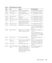
...with the system. Memory configuration does not support redundant memory. Retry the BIOS update. board. Decreasing available memory Faulty or improperly installed memory See "Troubleshooting System Memory" modules. Mismatched or unmatched DIMMs installed; Table 1-7. Redundant memory disabled! Installed memory modules are not the...been cleared. on page 120. faulty or improperly seated memory module(s). Ensure that all microprocessors have the same cache size and that they are properly installed. Remote Configuration request has Wait until the process is being processed. ...
...with the system. Memory configuration does not support redundant memory. Retry the BIOS update. board. Decreasing available memory Faulty or improperly installed memory See "Troubleshooting System Memory" modules. Mismatched or unmatched DIMMs installed; Table 1-7. Redundant memory disabled! Installed memory modules are not the...been cleared. on page 120. faulty or improperly seated memory module(s). Ensure that all microprocessors have the same cache size and that they are properly installed. Remote Configuration request has Wait until the process is being processed. ...
Hardware Owner's Manual (PDF)
Page 30
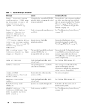
... Messages (continued) Message Causes Corrective Actions Error: Incorrect memory configuration. See "System Memory" on page 120. 30 About Your System Dell recommends purchasing memory upgrade kits directly from www.dell.com or your Dell sales agent to resolve the problem. Gate A20 failure ... Help" on page 147. General failure The operating system is usually followed by BIOS: DIMM x Rank y Faulty memory module(s). Invalid NVRAM configuration, Resource Re-allocated System detected and corrected a resource conflict. No action is properly installed. faulty system board See...
... Messages (continued) Message Causes Corrective Actions Error: Incorrect memory configuration. See "System Memory" on page 120. 30 About Your System Dell recommends purchasing memory upgrade kits directly from www.dell.com or your Dell sales agent to resolve the problem. Gate A20 failure ... Help" on page 147. General failure The operating system is usually followed by BIOS: DIMM x Rank y Faulty memory module(s). Invalid NVRAM configuration, Resource Re-allocated System detected and corrected a resource conflict. No action is properly installed. faulty system board See...


