Installing a SATA Optical Drive
Page 1
Dell™ PowerEdge™ 19x0 and 29x0 Systems Installing a SATA Optical Drive
Dell™ PowerEdge™ 19x0 and 29x0 Systems Installing a SATA Optical Drive

Installing a SATA Optical Drive
Page 3
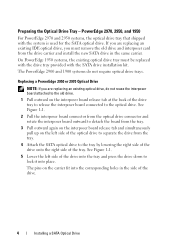
... center fan bracket. Installing a SATA Optical Drive 3 See "Removing the Bezel" in your Hardware Owner's Manual. 4 PowerEdge 1950 systems only: Disconnect and remove the SAS controller daughter card. Installing a SATA Optical Drive These instructions apply to Dell™ PowerEdge™ systems to remove the ... "Removing a SAS Controller Daughter Card" in which a SATA optical drive is being added, or in your Hardware Owner's Manual. 5 Disconnect the data and power cables from the back of the optical drive. 6 PowerEdge 2900 and 1900 systems only: Perform the following steps. See ...
... center fan bracket. Installing a SATA Optical Drive 3 See "Removing the Bezel" in your Hardware Owner's Manual. 4 PowerEdge 1950 systems only: Disconnect and remove the SAS controller daughter card. Installing a SATA Optical Drive These instructions apply to Dell™ PowerEdge™ systems to remove the ... "Removing a SAS Controller Daughter Card" in which a SATA optical drive is being added, or in your Hardware Owner's Manual. 5 Disconnect the data and power cables from the back of the optical drive. 6 PowerEdge 2900 and 1900 systems only: Perform the following steps. See ...
Installing a SATA Optical Drive
Page 4
The PowerEdge 2900 and 1900 systems do not reuse the interposer board attached to the old drive. 1 Pull outward on the interposer board release tab at the back of the drive. 4 Installing a SATA Optical Drive See Figure 1-1. 2 Pull the interposer board connector from the optical drive connector and rotate the interposer board outward to detach the board from...
The PowerEdge 2900 and 1900 systems do not reuse the interposer board attached to the old drive. 1 Pull outward on the interposer board release tab at the back of the drive. 4 Installing a SATA Optical Drive See Figure 1-1. 2 Pull the interposer board connector from the optical drive connector and rotate the interposer board outward to detach the board from...

Installing a SATA Optical Drive
Page 5
See Figure 1-2. Replacing the Optical Drive in a PowerEdge 2950 or 2970 System 2 1 3 4 5 6 7 1 optical drive 3 interposer 5 SATA power cable 7 optical drive carrier 2 interposer release latch 4 SATA cable 6 carrier latch Replacing a PowerEdge 1950 Optical Drive NOTE: The replacement drive tray provided in the installation kit must be used with the holes in the side of the SATA optical drive into the tray until the...
See Figure 1-2. Replacing the Optical Drive in a PowerEdge 2950 or 2970 System 2 1 3 4 5 6 7 1 optical drive 3 interposer 5 SATA power cable 7 optical drive carrier 2 interposer release latch 4 SATA cable 6 carrier latch Replacing a PowerEdge 1950 Optical Drive NOTE: The replacement drive tray provided in the installation kit must be used with the holes in the side of the SATA optical drive into the tray until the...

Installing a SATA Optical Drive
Page 6
... cable into position. 2 Connect the SATA cable (the end with a cable provided in a PowerEdge 1950 Drive Tray 2 3 1 4 5 1 optical drive 3 SATA power cable 5 optical drive carrier 2 SATA cable 4 carrier latch Installing the SATA Optical Drive - PowerEdge 1950 1 Insert the optical drive tray into the system until it is... Figure 1-2. c Connect the cable to the power supply bays. Installing a SATA Optical Drive in the optical drive kit. 4 Route the SATA cable to the SATA_A connector on top of the optical drive. 3 Connect the branching power cable to the back of the chipset shroud...
... cable into position. 2 Connect the SATA cable (the end with a cable provided in a PowerEdge 1950 Drive Tray 2 3 1 4 5 1 optical drive 3 SATA power cable 5 optical drive carrier 2 SATA cable 4 carrier latch Installing the SATA Optical Drive - PowerEdge 1950 1 Insert the optical drive tray into the system until it is... Figure 1-2. c Connect the cable to the power supply bays. Installing a SATA Optical Drive in the optical drive kit. 4 Route the SATA cable to the SATA_A connector on top of the optical drive. 3 Connect the branching power cable to the back of the chipset shroud...

Installing a SATA Optical Drive
Page 7
... card and reconnect the SAS cable. Installing a SATA Optical Drive 7 See "Closing the System" in your Hardware Owner's Manual. 6 Close the system. See "SAS Controller Daughter Card" in the PowerEdge 1950 2 1 3 4 6 5 1 SATA data cable 3 chipset shroud 5 SATA power cable 2 SATA_A connector on the system and attached peripherals. Figure 1-3. SATA Cable Routing in your Hardware Owner's Manual...
... card and reconnect the SAS cable. Installing a SATA Optical Drive 7 See "Closing the System" in your Hardware Owner's Manual. 6 Close the system. See "SAS Controller Daughter Card" in the PowerEdge 1950 2 1 3 4 6 5 1 SATA data cable 3 chipset shroud 5 SATA power cable 2 SATA_A connector on the system and attached peripherals. Figure 1-3. SATA Cable Routing in your Hardware Owner's Manual...

Installing a SATA Optical Drive
Page 8
...behind the central riser and connect the cable to the SATA_B connector on system board 2 cable retention bracket 3 SATA data cable 4 SATA power cable 5 optical drive 8 Installing a SATA Optical Drive See Figure 1-4. 7 Route the SATA cable along the top of the chassis and replace the cable retention bracket over the cable. 4 Remove the ... release latch and sliding the bracket toward the front of the system until the bracket detaches from the chassis slots. 6 Route the SATA cable in the cable channel in the PowerEdge 2950 and 2970 1 2 3 4 5 1 SATA_B connector on the system board.
...behind the central riser and connect the cable to the SATA_B connector on system board 2 cable retention bracket 3 SATA data cable 4 SATA power cable 5 optical drive 8 Installing a SATA Optical Drive See Figure 1-4. 7 Route the SATA cable along the top of the chassis and replace the cable retention bracket over the cable. 4 Remove the ... release latch and sliding the bracket toward the front of the system until the bracket detaches from the chassis slots. 6 Route the SATA cable in the cable channel in the PowerEdge 2950 and 2970 1 2 3 4 5 1 SATA_B connector on the system board.

Installing a SATA Optical Drive
Page 9
... the SATA Optical Drive - See Figure 1-5. - See Figure 1-5. - Installing a SATA Optical Drive 9 See "Closing the System" in your Hardware Owner's Manual. 6 Replace the fans in the optical drive kit and connect one end to the optical drive and the other to the CD/TBU connector on the system board. For a PowerEdge 2900, use the SATA_D connector. For a PowerEdge 2900 system...
... the SATA Optical Drive - See Figure 1-5. - See Figure 1-5. - Installing a SATA Optical Drive 9 See "Closing the System" in your Hardware Owner's Manual. 6 Replace the fans in the optical drive kit and connect one end to the optical drive and the other to the CD/TBU connector on the system board. For a PowerEdge 2900, use the SATA_D connector. For a PowerEdge 2900 system...

Installing a SATA Optical Drive
Page 10
SATA Cable Routing in your Hardware Owner's Manual. 10 Reconnect the system to power and turn on system board 8 Reconnect the cables to the SAS controller daughter card. 9 Close the system. See "Closing the System" in a PowerEdge 2900 or 1900 3 2 4 5 1 1 optical drive 3 SATA data cable 5 SATA power connector on SAS backplane (PowerEdge 2900 only) 2 SATA power cable 4 SATA connector on the system and attached peripherals. 10 Installing a SATA Optical Drive Figure 1-5.
SATA Cable Routing in your Hardware Owner's Manual. 10 Reconnect the system to power and turn on system board 8 Reconnect the cables to the SAS controller daughter card. 9 Close the system. See "Closing the System" in a PowerEdge 2900 or 1900 3 2 4 5 1 1 optical drive 3 SATA data cable 5 SATA power connector on SAS backplane (PowerEdge 2900 only) 2 SATA power cable 4 SATA connector on the system and attached peripherals. 10 Installing a SATA Optical Drive Figure 1-5.
Getting Started Guide
Page 5
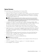
...Sequence. • Support for up to a maximum of 48 GB by dividing processor operations between independent processors. The upgrade kit from Dell. System Features The major hardware and software features of your system by installing a second processor, you must use an operating system ... hot-pluggable Serial-Attached SCSI (SAS) or SATA hard drives (eight 3.5-inch internal hard drives with the 1x2 flexbay bracket removed. • An optional single, 1.44-MB, 3.5-inch diskette drive. • An optional CD, DVD, or combination CD-RW/DVD drive. NOTE: DVD devices are installed. •...
...Sequence. • Support for up to a maximum of 48 GB by dividing processor operations between independent processors. The upgrade kit from Dell. System Features The major hardware and software features of your system by installing a second processor, you must use an operating system ... hot-pluggable Serial-Attached SCSI (SAS) or SATA hard drives (eight 3.5-inch internal hard drives with the 1x2 flexbay bracket removed. • An optional single, 1.44-MB, 3.5-inch diskette drive. • An optional CD, DVD, or combination CD-RW/DVD drive. NOTE: DVD devices are installed. •...
Getting Started Guide
Page 12
...type Expansion Bus Bus type Expansion slots PCI-X PCIe Memory Architecture Memory module sockets Memory module capacities Minimum RAM Maximum RAM Drives Hard drives Diskette drive Optical drive Flash drive One or two Dual-Core Intel Xeon Processors 5000 Sequence PCI, PCI-X, PCIe two full-height, full-length 3.3-V, 64...or 4 GB 512 MB (two 256-MB module) 48 GB up to ten 3.5-inch, internal, hot-plug SAS or SATA • eight drives in the internal drive bay • two drives in the optional 1x2 flexbay backplane expansion one optional 3.5-inch, 1.44-MB external optional USB 3.5-inch, 1.44-MB one ...
...type Expansion Bus Bus type Expansion slots PCI-X PCIe Memory Architecture Memory module sockets Memory module capacities Minimum RAM Maximum RAM Drives Hard drives Diskette drive Optical drive Flash drive One or two Dual-Core Intel Xeon Processors 5000 Sequence PCI, PCI-X, PCIe two full-height, full-length 3.3-V, 64...or 4 GB 512 MB (two 256-MB module) 48 GB up to ten 3.5-inch, internal, hot-plug SAS or SATA • eight drives in the internal drive bay • two drives in the optional 1x2 flexbay backplane expansion one optional 3.5-inch, 1.44-MB external optional USB 3.5-inch, 1.44-MB one ...
Hardware Owner's Manual (PDF)
Page 4
... Before You Begin 55 Removing a Drive Blank 56 Installing a Drive Blank 56 Removing a Hot-Plug Hard Drive 56 Installing a Hot-Plug Hard Drive 56 Replacing a Hard-Drive Carrier 58 Removing a Hard Drive From a Hard-Drive Carrier 58 Installing a SAS Hard Drive Into a SATAu Drive Carrier 58 Installing a SATA Hard Drive Into a SATA Drive Carrier 59 Installing a SATA Hard Drive and Interposer Card Into a SATAu Hard...
... Before You Begin 55 Removing a Drive Blank 56 Installing a Drive Blank 56 Removing a Hot-Plug Hard Drive 56 Installing a Hot-Plug Hard Drive 56 Replacing a Hard-Drive Carrier 58 Removing a Hard Drive From a Hard-Drive Carrier 58 Installing a SAS Hard Drive Into a SATAu Drive Carrier 58 Installing a SATA Hard Drive Into a SATA Drive Carrier 59 Installing a SATA Hard Drive and Interposer Card Into a SATAu Hard...

Hardware Owner's Manual (PDF)
Page 13
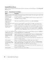
...Eight hot-pluggable bays for two additional 3.5-inch, hot-pluggable SAS or SATA hard drives. Table 1-2. Optional flex bay drive bracket with 1x2 SAS backplane for 3.5-inch SAS or SATA hard drives connected to AC power and an error has been detected, the LCD lights...) Item Component Icon 3 System identification button 4 LCD panel 5 USB connectors (2) 6 Video connector 7 Diskette drive 8 Hard drives 9 Flex bay 10 Tape backup unit 11 Optical drive Description The identification buttons on the front and back of the buttons is connected to a 1x8 SAS backplane. ...
...Eight hot-pluggable bays for two additional 3.5-inch, hot-pluggable SAS or SATA hard drives. Table 1-2. Optional flex bay drive bracket with 1x2 SAS backplane for 3.5-inch SAS or SATA hard drives connected to AC power and an error has been detected, the LCD lights...) Item Component Icon 3 System identification button 4 LCD panel 5 USB connectors (2) 6 Video connector 7 Diskette drive 8 Hard drives 9 Flex bay 10 Tape backup unit 11 Optical drive Description The identification buttons on the front and back of the buttons is connected to a 1x8 SAS backplane. ...
Hardware Owner's Manual (PDF)
Page 38
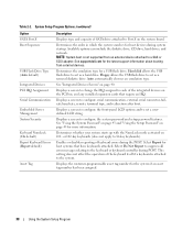
... System boot is attached to the system. Floppy allows the USB flash drive to Port X on page 45 for host systems that require an IRQ. Enables or disables reporting of SATA drive attached to act as a hard drive. Select Do Not Report to suppress all error messages relating to each of...-key keyboards (does not apply to configure the system password and setup password features. Select Report for more information. See support.dell.com for a USB flash drive. Table 2-2. Determines the order in which the system searches for the system if an asset tag number has been assigned. 38...
... System boot is attached to the system. Floppy allows the USB flash drive to Port X on page 45 for host systems that require an IRQ. Enables or disables reporting of SATA drive attached to act as a hard drive. Select Do Not Report to suppress all error messages relating to each of...-key keyboards (does not apply to configure the system password and setup password features. Select Report for more information. See support.dell.com for a USB flash drive. Table 2-2. Determines the order in which the system searches for the system if an asset tag number has been assigned. 38...
Hardware Owner's Manual (PDF)
Page 40
...This option appears only if a SAS (Enabled default) controller is installed. Diskette Controller (Auto default) Enables or disables the system's diskette drive controller. Embedded Gb NIC1 (Enabled with PXE default) Enables or disables the system's integrated NIC1. This option appears only if a SAS RAID...default) On, Only Back Ports On, and All Ports Off. Changes take effect after the system reboots. Embedded SATA (Off default) Allows the integrated SATA controller to be used to write to the channel. IDE CD-ROM Controller Enables the integrated IDE controller. TOE ...
...This option appears only if a SAS (Enabled default) controller is installed. Diskette Controller (Auto default) Enables or disables the system's diskette drive controller. Embedded Gb NIC1 (Enabled with PXE default) Enables or disables the system's integrated NIC1. This option appears only if a SAS RAID...default) On, Only Back Ports On, and All Ports Off. Changes take effect after the system reboots. Embedded SATA (Off default) Allows the integrated SATA controller to be used to write to the channel. IDE CD-ROM Controller Enables the integrated IDE controller. TOE ...
Hardware Owner's Manual (PDF)
Page 54
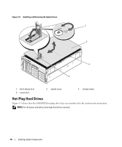
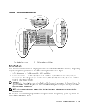
Installing and Removing the System Cover 1 2 3 4 1 latch release lock 4 cover latch 2 system cover 3 chassis hooks Hot-Plug Hard Drives Figure 3-5 shows how the SAS/SATA hot-plug drive bays are reversed. 54 Installing System Components NOTE: For the tower orientation, drive bays 8 and 9 are numbered in the rack-mount orientation. Figure 3-4.
Installing and Removing the System Cover 1 2 3 4 1 latch release lock 4 cover latch 2 system cover 3 chassis hooks Hot-Plug Hard Drives Figure 3-5 shows how the SAS/SATA hot-plug drive bays are reversed. 54 Installing System Components NOTE: For the tower orientation, drive bays 8 and 9 are numbered in the rack-mount orientation. Figure 3-4.
Hardware Owner's Manual (PDF)
Page 55
... tested and approved for the optional SAS RAID controller daughter card to use with the operating system to support hotplug drive removal and insertion. Usable with either a SAS hard drive or a SATA hard drive with a SATA hard drive. • SATAu drive carrier - Figure 3-5. You may need to ensure that the host adapter is recommended that makes the...
... tested and approved for the optional SAS RAID controller daughter card to use with the operating system to support hotplug drive removal and insertion. Usable with either a SAS hard drive or a SATA hard drive with a SATA hard drive. • SATAu drive carrier - Figure 3-5. You may need to ensure that the host adapter is recommended that makes the...

Hardware Owner's Manual (PDF)
Page 59
.... See Figure 3-8. 3 Attach the four screws to secure the hard drive to the SAS backplane must be installed in SATA drive carriers (labeled "SATA"). Installing a SAS Hard Drive Into a Drive Carrier 1 2 3 1 screws (4) 2 SATAu drive carrier 3 SAS hard drive Installing a SATA Hard Drive Into a SATA Drive Carrier NOTE: SATA hard drives that connect directly to the hard-drive carrier. See Figure 3-8. Installing System Components 59 Figure 3-7.
.... See Figure 3-8. 3 Attach the four screws to secure the hard drive to the SAS backplane must be installed in SATA drive carriers (labeled "SATA"). Installing a SAS Hard Drive Into a Drive Carrier 1 2 3 1 screws (4) 2 SATAu drive carrier 3 SAS hard drive Installing a SATA Hard Drive Into a SATA Drive Carrier NOTE: SATA hard drives that connect directly to the hard-drive carrier. See Figure 3-8. Installing System Components 59 Figure 3-7.

Hardware Owner's Manual (PDF)
Page 60
... 3-9, align the bottom rear screw hole on the hard drive with the hole labeled "SATAu" on the hard drive carrier. Installing a SATA Hard Drive Into a SATA Drive Carrier 1 2 3 1 screws (4) 2 SATA drive carrier 3 SATA hard drive Installing a SATA Hard Drive and Interposer Card Into a SATAu Hard-Drive Carrier NOTE: When you install a SATA hard drive into the SATAu hard-drive carrier with the rear of the hard...
... 3-9, align the bottom rear screw hole on the hard drive with the hole labeled "SATAu" on the hard drive carrier. Installing a SATA Hard Drive Into a SATA Drive Carrier 1 2 3 1 screws (4) 2 SATA drive carrier 3 SATA hard drive Installing a SATA Hard Drive and Interposer Card Into a SATAu Hard-Drive Carrier NOTE: When you install a SATA hard drive into the SATAu hard-drive carrier with the rear of the hard...

Hardware Owner's Manual (PDF)
Page 178
... processor, 89 RAC card, 87 RAID battery, 96 SAS backplane (1x8), 93 SAS controller daughter card, 99 SAS hard drive in a SATAu drive carrier, 58 SATA hard drive in a SATA drive carrier, 59 SATA hard drive in a SATAu drive carrier, 60 system battery, 77 system board, 109 tape backup unit, 71 IRQs avoiding conflicts, 116 configuring, 38 line assignments...
... processor, 89 RAC card, 87 RAID battery, 96 SAS backplane (1x8), 93 SAS controller daughter card, 99 SAS hard drive in a SATAu drive carrier, 58 SATA hard drive in a SATA drive carrier, 59 SATA hard drive in a SATAu drive carrier, 60 system battery, 77 system board, 109 tape backup unit, 71 IRQs avoiding conflicts, 116 configuring, 38 line assignments...


