
Installing a SATA Optical Drive
Page 9
... cable to the SATA connector on the system board. See "Replacing the Center Fan Bracket" in your Hardware Owner's Manual. 6 Replace the fans in the center fan bracket. 7 Route the SATA cable to the system board over the top of the optical drive. 4 Use the appropriate power cable provided in the optical drive kit and connect one end to the optical drive and the other to power and turn on the system backplane. For a PowerEdge 2900, use the SATA_D connector. 9 Replace...
... cable to the SATA connector on the system board. See "Replacing the Center Fan Bracket" in your Hardware Owner's Manual. 6 Replace the fans in the center fan bracket. 7 Route the SATA cable to the system board over the top of the optical drive. 4 Use the appropriate power cable provided in the optical drive kit and connect one end to the optical drive and the other to power and turn on the system backplane. For a PowerEdge 2900, use the SATA_D connector. 9 Replace...
Getting Started Guide
Page 6
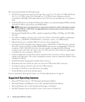
... 1280 x 1024. PCIe slots accommodate up to a SAS or SCSI adapter, including SAS 5/E, PERC 5/E, or PERC 4e/DC. See support.dell.com for remote systems management. • An integrated VGA-compatible video subsystem with 256 MB of supporting a diskette drive, a CD-ROM or DVD-ROM drive, a keyboard, a mouse, or a USB flash drive. • Optional remote access controller (RAC) for the latest support information about specific features, see "Technical Specifications" on the front and back panels. This video subsystem contains...
... 1280 x 1024. PCIe slots accommodate up to a SAS or SCSI adapter, including SAS 5/E, PERC 5/E, or PERC 4e/DC. See support.dell.com for remote systems management. • An integrated VGA-compatible video subsystem with 256 MB of supporting a diskette drive, a CD-ROM or DVD-ROM drive, a keyboard, a mouse, or a USB flash drive. • Optional remote access controller (RAC) for the latest support information about specific features, see "Technical Specifications" on the front and back panels. This video subsystem contains...
Hardware Owner's Manual (PDF)
Page 11
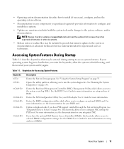
... BMC. See the BMC User's Guide for Accessing System Features Keystroke Description Enters the System Setup program. If you to selected DRAC configuration settings. Keystrokes for more information, see "Integrated Devices Screen" on setup and use of DRAC. Opens the utility partition, allowing you have PXE support enabled through the System Setup Program (see the documentation for your SAS adapter User's Guide for more information. Enters the RAID configuration utility, which allows access to the system event log...
... BMC. See the BMC User's Guide for Accessing System Features Keystroke Description Enters the System Setup program. If you to selected DRAC configuration settings. Keystrokes for more information, see "Integrated Devices Screen" on setup and use of DRAC. Opens the utility partition, allowing you have PXE support enabled through the System Setup Program (see the documentation for your SAS adapter User's Guide for more information. Enters the RAID configuration utility, which allows access to the system event log...
Hardware Owner's Manual (PDF)
Page 22
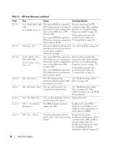
... BIOS has reported a PCIe fatal error on a component that there has been an error in PCI configuration persists, see "Troubleshooting space at bus ##, device ##, function ##. See "Troubleshooting a Hard Drive" on page 147. If the problem persists, see "Troubleshooting Expansion Cards" on page 131. CPU & Firmware Mismatch The BMC firmware does not support the CPU. See the BMC User's Guide for more information on page 112. 22 About Your System See "Installing the Power Distribution Board" on setup and use of BMC...
... BIOS has reported a PCIe fatal error on a component that there has been an error in PCI configuration persists, see "Troubleshooting space at bus ##, device ##, function ##. See "Troubleshooting a Hard Drive" on page 147. If the problem persists, see "Troubleshooting Expansion Cards" on page 131. CPU & Firmware Mismatch The BMC firmware does not support the CPU. See the BMC User's Guide for more information on page 112. 22 About Your System See "Installing the Power Distribution Board" on setup and use of BMC...
Hardware Owner's Manual (PDF)
Page 32
... installing or updating the RAID firmware. See "Troubleshooting the System Battery" on page 147. "Using the System Setup Program" on the boot hard drive. Warning! Embedded RAID firmware does not respond. DIMM y Ensure that only Dell-qualified memory is used . Utility partition not available The key was pressed during POST, but no utility partition exists on page 35. See the CDs that came with an error. See "Microprocessor" on page 89. Dell recommends purchasing memory upgrade kits...
... installing or updating the RAID firmware. See "Troubleshooting the System Battery" on page 147. "Using the System Setup Program" on the boot hard drive. Warning! Embedded RAID firmware does not respond. DIMM y Ensure that only Dell-qualified memory is used . Utility partition not available The key was pressed during POST, but no utility partition exists on page 35. See the CDs that came with an error. See "Microprocessor" on page 89. Dell recommends purchasing memory upgrade kits...
Hardware Owner's Manual (PDF)
Page 38
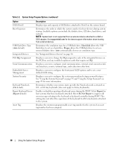
... as a removal diskette drive. Determines whether your system starts up with the NumLock mode activated on 101- Hard disk allows the USB flash drive to each of keyboard errors during system startup. Select Do Not Report to suppress all error messages relating to a SAS or SCSI adapter. Displays the customer-programmable asset tag number for host systems that require an IRQ. See support.dell.com for a USB flash drive. Determines the emulation type for...
... as a removal diskette drive. Determines whether your system starts up with the NumLock mode activated on 101- Hard disk allows the USB flash drive to each of keyboard errors during system startup. Select Do Not Report to suppress all error messages relating to a SAS or SCSI adapter. Displays the customer-programmable asset tag number for host systems that require an IRQ. See support.dell.com for a USB flash drive. Determines the emulation type for...
Hardware Owner's Manual (PDF)
Page 40
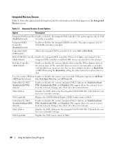
... if a SAS (Enabled default) controller is installed. Embedded SATA (Off default) Allows the integrated SATA controller to be used to write to Off or ATA Mode. When set to a disk. User Accessible USB Ports Enables or disables the system's user accessible USB ports. Embedded Gb NIC2 (Enabled without PXE, Enabled with PXE default) Enables or disables the system's integrated NIC1. Integrated Devices Screen Table 2-4 lists the options and descriptions for the integrated 10/100/1000 NIC. This option appears only if a SAS RAID controller is installed. When...
... if a SAS (Enabled default) controller is installed. Embedded SATA (Off default) Allows the integrated SATA controller to be used to write to Off or ATA Mode. When set to a disk. User Accessible USB Ports Enables or disables the system's user accessible USB ports. Embedded Gb NIC2 (Enabled without PXE, Enabled with PXE default) Enables or disables the system's integrated NIC1. Integrated Devices Screen Table 2-4 lists the options and descriptions for the integrated 10/100/1000 NIC. This option appears only if a SAS RAID controller is installed. When...

Hardware Owner's Manual (PDF)
Page 43
... data encryption programs. NOTICE: Anyone can disable the password by a jumper setting, the system password is Unlocked. If you forget your password, you cannot change the system password. Assigning a System Password Before you cannot change or enter a new system password. If your data requires more security, use of security for the System Password option is Not Enabled and the Password Status field is Disabled, and you cannot operate your password. See "Disabling a Forgotten Password...
... data encryption programs. NOTICE: Anyone can disable the password by a jumper setting, the system password is Unlocked. If you forget your password, you cannot change the system password. Assigning a System Password Before you cannot change or enter a new system password. If your data requires more security, use of security for the System Password option is Not Enabled and the Password Status field is Disabled, and you cannot operate your password. See "Disabling a Forgotten Password...
Hardware Owner's Manual (PDF)
Page 124
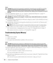
... memory setting, go to recognize the fan and determine whether it is working inside the computer and protecting against electrostatic discharge. 1 Run the appropriate online diagnostic test. If an error message does not appear, continue to step 13. 124 Troubleshooting Your System See "Using Server Administrator Diagnostics" on page 53. See "Opening the System" on , only replace one fan at a time. 3 Locate the faulty fan indicated by removing...
... memory setting, go to recognize the fan and determine whether it is working inside the computer and protecting against electrostatic discharge. 1 Run the appropriate online diagnostic test. If an error message does not appear, continue to step 13. 124 Troubleshooting Your System See "Using Server Administrator Diagnostics" on page 53. See "Opening the System" on , only replace one fan at a time. 3 Locate the faulty fan indicated by removing...

Hardware Owner's Manual (PDF)
Page 126
... verify that a power cable is configured correctly. See "Opening the System" on page 53. 6 Ensure that the diskette drive interface cable is securely connected to the diskette drive and the system board. 7 Ensure that the diskette drive is properly connected to the drive. 8 Close the system. Troubleshooting a Diskette Drive Problem • Error message indicates a diskette drive problem. See "Using the System Setup Program" on page 50. 3 Run the appropriate online diagnostic test. 13 Perform the...
... verify that a power cable is configured correctly. See "Opening the System" on page 53. 6 Ensure that the diskette drive interface cable is securely connected to the diskette drive and the system board. 7 Ensure that the diskette drive is properly connected to the drive. 8 Close the system. Troubleshooting a Diskette Drive Problem • Error message indicates a diskette drive problem. See "Using the System Setup Program" on page 50. 3 Run the appropriate online diagnostic test. 13 Perform the...
Hardware Owner's Manual (PDF)
Page 130
... operating system and the controller daughter card. Problem • Error message indicates a problem with another bay but does not function in their connectors. See "Using Server Administrator Diagnostics" on page 147. 7 If you have intermittent problems. Replace the hard-drive carrier. See "Getting Help" on page 135. 2 Enter the System Setup program and ensure that the SAS or SAS RAID controller daughter card is functioning properly. See "Opening the System" on the SAS backplane...
... operating system and the controller daughter card. Problem • Error message indicates a problem with another bay but does not function in their connectors. See "Using Server Administrator Diagnostics" on page 147. 7 If you have intermittent problems. Replace the hard-drive carrier. See "Getting Help" on page 135. 2 Enter the System Setup program and ensure that the SAS or SAS RAID controller daughter card is functioning properly. See "Opening the System" on the SAS backplane...
Hardware Owner's Manual (PDF)
Page 170
... the processor and a peripheral. Direct memory access. DRAM - DVD - EMI - Embedded remote access. Your system contains an expansion bus that plugs into IP addresses, such as the operating system, memory, peripherals, expansion cards, and asset tag. An add-in memory modules that controls the transfer of automatically assigning an IP address to DMI, components include operating systems, computer systems, expansion cards, and peripherals that component. A technology in card, such as a NIC or SCSI adapter, that...
... the processor and a peripheral. Direct memory access. DRAM - DVD - EMI - Embedded remote access. Your system contains an expansion bus that plugs into IP addresses, such as the operating system, memory, peripherals, expansion cards, and asset tag. An add-in memory modules that controls the transfer of automatically assigning an IP address to DMI, components include operating systems, computer systems, expansion cards, and peripherals that component. A technology in card, such as a NIC or SCSI adapter, that...
Hardware Owner's Manual (PDF)
Page 174
... changing settings in an array. serial port - The volume of disks in the configuration software for technical support. striping - Because the System Setup program is the same on the system used to identify it consults the system.ini file to the system BIOS and then display an error message on a multiple-disk system. TCP/IP - When such devices are video standards for the Windows operating environment. SDRAM - Allows hard drives to report errors and failures...
... changing settings in an array. serial port - The volume of disks in the configuration software for technical support. striping - Because the System Setup program is the same on the system used to identify it consults the system.ini file to the system BIOS and then display an error message on a multiple-disk system. TCP/IP - When such devices are video standards for the Windows operating environment. SDRAM - Allows hard drives to report errors and failures...

Hardware Owner's Manual (PDF)
Page 175
... the use of use on a network hub or switch used to file service for multiple USB-compliant devices, such as the number of pixels across by the number of options for the Windows operating environment. Video graphics array. Watt-hour(s). Universal Internet Exchange. A program used to connect to a telephone line. A type of colors that contain optional settings for video adapters with the desired number of an electrical failure. V - video driver - The amount of video memory installed primarily...
... the use of use on a network hub or switch used to file service for multiple USB-compliant devices, such as the number of pixels across by the number of options for the Windows operating environment. Video graphics array. Watt-hour(s). Universal Internet Exchange. A program used to connect to a telephone line. A type of colors that contain optional settings for video adapters with the desired number of an electrical failure. V - video driver - The amount of video memory installed primarily...
Hardware Owner's Manual (PDF)
Page 177
... panel, 52 removing, 51 blank hard drive, 56 power supply, 64 BMC. See baseboard management controller boot drive configuring, 105 boot sequence, 38 C cabling the SAS backplanes, 99 CD drive troubleshooting, 127 checking equipment, 116 closing the system, 53 configuring boot drive, 105 memory, 84 connecting external devices, 16 connectors SAS backplane (1x8), 142 system board, 141 control panel installing, 106 removing, 105 cooling fans removing and installing, 65 troubleshooting, 123 cooling shroud installing, 81 removing, 79 cooling shroud fan, 66 cover closing, 53 opening, 53 CPU setup...
... panel, 52 removing, 51 blank hard drive, 56 power supply, 64 BMC. See baseboard management controller boot drive configuring, 105 boot sequence, 38 C cabling the SAS backplanes, 99 CD drive troubleshooting, 127 checking equipment, 116 closing the system, 53 configuring boot drive, 105 memory, 84 connecting external devices, 16 connectors SAS backplane (1x8), 142 system board, 141 control panel installing, 106 removing, 105 cooling fans removing and installing, 65 troubleshooting, 123 cooling shroud installing, 81 removing, 79 cooling shroud fan, 66 cover closing, 53 opening, 53 CPU setup...

Hardware Owner's Manual (PDF)
Page 178
..., 26 expansion cards installing, 68 removing, 70 troubleshooting, 131 expansion slots, 68 expansion-bay bracket installing, 110 removing, 108 external devices connecting, 16 F fan bracket back, 82 center, 81 cooling shroud, 66 fans, 64 installing and removing, 65 numbered, 65 features back-panel, 16 front-panel, 12 flex bay drive bracket installing, 95 removing, 94 G guidelines for memory installation, 84 H hard drive indicator codes, 14 installing, 56 installing SAS in a SATAu drive carrier, 58 installing SATA in a SATA drive carrier, 59 installing SATA in a SATAu drive carrier, 60 removing...
..., 26 expansion cards installing, 68 removing, 70 troubleshooting, 131 expansion slots, 68 expansion-bay bracket installing, 110 removing, 108 external devices connecting, 16 F fan bracket back, 82 center, 81 cooling shroud, 66 fans, 64 installing and removing, 65 numbered, 65 features back-panel, 16 front-panel, 12 flex bay drive bracket installing, 95 removing, 94 G guidelines for memory installation, 84 H hard drive indicator codes, 14 installing, 56 installing SAS in a SATAu drive carrier, 58 installing SATA in a SATA drive carrier, 59 installing SATA in a SATAu drive carrier, 60 removing...
Information Update
Page 10
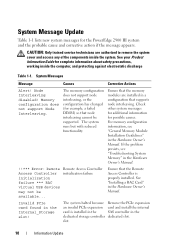
... remove the system cover and access any of the components inside the computer, and protecting against electrostatic discharge Table 1-1. Check other system messages for additional information for the PowerEdge 2900 III system and the probable cause and corrective action if the message appears. For memory configuration information, see "Troubleshooting System Memory" in the Hardware Owner's Manual. !!*** Error: Remote Access Controller initialization failure *** RAC virtual USB devices may not be supported. slot. 10 Information Update Remote Access Controller initialization...
... remove the system cover and access any of the components inside the computer, and protecting against electrostatic discharge Table 1-1. Check other system messages for additional information for the PowerEdge 2900 III system and the probable cause and corrective action if the message appears. For memory configuration information, see "Troubleshooting System Memory" in the Hardware Owner's Manual. !!*** Error: Remote Access Controller initialization failure *** RAC virtual USB devices may not be supported. slot. 10 Information Update Remote Access Controller initialization...
Information Update
Page 11
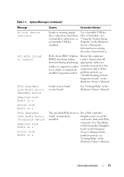
...) Message No boot device available PCI BIOS failed to the loose; PCIe device BIOS (Option Reseat the expansion ROM) checksum failure card(s). problem persists, see "Getting Help" in the Hardware Owner's Manual. The specified PCIe device is n Causes Corrective Actions Faulty or missing optical Use a bootable USB key, drive subsystem, hard drive, CD, or hard drive. Faulty system board or riser board. See "Getting Help" in the Hardware Owner's Manual. faulty or improperly expansion card(s). See "Installing a SAS Controller Daughter Card" in the Hardware Owner...
...) Message No boot device available PCI BIOS failed to the loose; PCIe device BIOS (Option Reseat the expansion ROM) checksum failure card(s). problem persists, see "Getting Help" in the Hardware Owner's Manual. The specified PCIe device is n Causes Corrective Actions Faulty or missing optical Use a bootable USB key, drive subsystem, hard drive, CD, or hard drive. Faulty system board or riser board. See "Getting Help" in the Hardware Owner's Manual. faulty or improperly expansion card(s). See "Installing a SAS Controller Daughter Card" in the Hardware Owner...

Information Update
Page 14
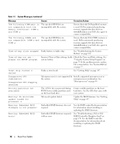
See "General Memory Module Installation Guidelines" in the Hardware Owner's Manual. Replace the faulty media. The system runs but with reduced functionality. For hard drive problems, see "Troubleshooting System Memory" in a valid configuration. Faulty USB device, USB medium, optical drive assembly, hard drive, or hard-drive subsystem. Reseat the USB device or USB cable. For information on the PowerEdge 2900 III system and the probable cause for each message. LCD Status Messages Update Table 1-2 lists updates to events recorded in the system event log (SEL). The LCD ...
See "General Memory Module Installation Guidelines" in the Hardware Owner's Manual. Replace the faulty media. The system runs but with reduced functionality. For hard drive problems, see "Troubleshooting System Memory" in a valid configuration. Faulty USB device, USB medium, optical drive assembly, hard drive, or hard-drive subsystem. Reseat the USB device or USB cable. For information on the PowerEdge 2900 III system and the probable cause for each message. LCD Status Messages Update Table 1-2 lists updates to events recorded in the system event log (SEL). The LCD ...
Information Update
Page 19
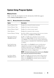
... power mode of video memory. When set to Spare Mode, the first rank of memory on the Memory Information screen. Displays the amount of the memory. Enables or disables the redundant memory feature. When set to Disabled, the memory runs at a reduced speed to Disabled, the system can support Non-Uniform Memory architecture (NUMA) (asymmetric) memory configurations. Information Update 19 System Setup Program Update Memory Screen Table 1-3 lists the descriptions for the information fields that appear on each DIMM...
... power mode of video memory. When set to Spare Mode, the first rank of memory on the Memory Information screen. Displays the amount of the memory. Enables or disables the redundant memory feature. When set to Disabled, the memory runs at a reduced speed to Disabled, the system can support Non-Uniform Memory architecture (NUMA) (asymmetric) memory configurations. Information Update 19 System Setup Program Update Memory Screen Table 1-3 lists the descriptions for the information fields that appear on each DIMM...


