
Installing the 1 x 2 SCSI Backplane
Page 5
...about safety precautions, working inside the system. See your system is installed in Figure 1-1. 4 Open the system. See the Dell Support website at support.dell.com for the latest BIOS version for detailed instructions on using the System Setup program. 2 Update the BIOS. This kit ...to step 4. Before You Begin NOTICE: Before you shut down the system to the latest version. Installing the 1 x 2 Module 1 Remove the front bezel (if applicable). 2 Turn off the system, including any of these settings. Before you install the backplane, update the BIOS to install the backplane: 1...
...about safety precautions, working inside the system. See your system is installed in Figure 1-1. 4 Open the system. See the Dell Support website at support.dell.com for the latest BIOS version for detailed instructions on using the System Setup program. 2 Update the BIOS. This kit ...to step 4. Before You Begin NOTICE: Before you shut down the system to the latest version. Installing the 1 x 2 Module 1 Remove the front bezel (if applicable). 2 Turn off the system, including any of these settings. Before you install the backplane, update the BIOS to install the backplane: 1...
Installing the 1 x 2 SCSI Backplane
Page 10
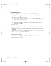
...fans or the cooling vents. 3 Slide the drive tray to the operating position. See your system User's Guide for the latest firmware updates. 9 Replace the bezel (if applicable). 1-8 Installing the 1 x 2 SCSI Module You may have been loosened during the procedure. 2 Arrange the cables so that they do not ... 6 Reconnect the system to its electrical outlet and turn the system on the system cover or block the airflow of the system. www.dell.com | support.dell.com F6590bk0.book Page 8 Tuesday, July 6, 2004 4:33 PM Completing the Installation 1 Check all cable connections that may also need to...
...fans or the cooling vents. 3 Slide the drive tray to the operating position. See your system User's Guide for the latest firmware updates. 9 Replace the bezel (if applicable). 1-8 Installing the 1 x 2 SCSI Module You may have been loosened during the procedure. 2 Arrange the cables so that they do not ... 6 Reconnect the system to its electrical outlet and turn the system on the system cover or block the airflow of the system. www.dell.com | support.dell.com F6590bk0.book Page 8 Tuesday, July 6, 2004 4:33 PM Completing the Installation 1 Check all cable connections that may also need to...
Installing the SCSI Backplane Daughter Card
Page 5
This document provides information about safety precautions, working inside the system. NOTE: See your Dell™ PowerEdge™ 2800 or 2850 system by its edges with the card connector facing the SCSI backplane board. 7 Insert the card connector into the SCSI .... In a split backplane configuration, the hard-drives are fully seated into the daughter card connector on the daughter card are arranged in a PowerEdge 2800 System 1 Remove the bezel (if applicable). 2 Unpack the SCSI backplane daughter card kit. 3 Turn off the system, including any of the front panel and slide ...
This document provides information about safety precautions, working inside the system. NOTE: See your Dell™ PowerEdge™ 2800 or 2850 system by its edges with the card connector facing the SCSI backplane board. 7 Insert the card connector into the SCSI .... In a split backplane configuration, the hard-drives are fully seated into the daughter card connector on the daughter card are arranged in a PowerEdge 2800 System 1 Remove the bezel (if applicable). 2 Unpack the SCSI backplane daughter card kit. 3 Turn off the system, including any of the front panel and slide ...

Installing the SCSI Backplane Daughter Card
Page 6
... SCSI channel A (channel 0) on the controller card to connector SCSIB on the SCSI backplane. See your system's User's Guide for more information. 13 Replace the bezel (if applicable). 1-4 Installing the SCSI Backplane Daughter Card b Connect SCSI channel B (channel 1) on the controller card to SCSIA on the SCSI backplane. b Rotate the drive... 1, 2, and 3. Installing the SCSI Daughter Card SCSI backplane board SCSI daughter card standoffs (2) 8 To use an optional RAID controller card in the operating position. www.dell.com | support.dell.com Figure 1-1.
... SCSI channel A (channel 0) on the controller card to connector SCSIB on the SCSI backplane. See your system's User's Guide for more information. 13 Replace the bezel (if applicable). 1-4 Installing the SCSI Backplane Daughter Card b Connect SCSI channel B (channel 1) on the controller card to SCSIA on the SCSI backplane. b Rotate the drive... 1, 2, and 3. Installing the SCSI Daughter Card SCSI backplane board SCSI daughter card standoffs (2) 8 To use an optional RAID controller card in the operating position. www.dell.com | support.dell.com Figure 1-1.
Installing the SCSI Backplane Daughter Card
Page 7
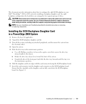
The SCSI backplane daughter card connector and card guide are located in a PowerEdge 2850 System 1 Unpack the SCSI backplane board daughter card kit. 2 Turn off the system, including any attached peripherals, and disconnect the system from the backplane ... backplane retention lever retention peg on the back of the control panel cable and pull the cable connector away from the electrical outlet. 3 Remove the bezel (if applicable). 4 Open the system. 5 Grasp the plastic tab on card SCSI daughter card backplane connector SCSI backplane SCSI daughter card guide SCSI daughter card...
The SCSI backplane daughter card connector and card guide are located in a PowerEdge 2850 System 1 Unpack the SCSI backplane board daughter card kit. 2 Turn off the system, including any attached peripherals, and disconnect the system from the backplane ... backplane retention lever retention peg on the back of the control panel cable and pull the cable connector away from the electrical outlet. 3 Remove the bezel (if applicable). 4 Open the system. 5 Grasp the plastic tab on card SCSI daughter card backplane connector SCSI backplane SCSI daughter card guide SCSI daughter card...

Installing the SCSI Backplane Daughter Card
Page 9
See your system's User's Guide for more information. 13 Replace the bezel (if applicable). NOTE: If a cable is configured correctly. b Connect SCSI channel B (channel 1) on the controller card to connector SCSIB on the SCSI backplane. This channel ...
See your system's User's Guide for more information. 13 Replace the bezel (if applicable). NOTE: If a cable is configured correctly. b Connect SCSI channel B (channel 1) on the controller card to connector SCSIB on the SCSI backplane. This channel ...
Processor Upgrade Installation Guide
Page 5
...system BIOS information on removing or replacing components. NOTE: See your system is upgradeable to accommodate secondary processors. See www.dell.com and support.dell.com for the primary processor on the system board, other ZIF sockets might adhere to cool before handling. Adding or ... website at support.dell.com, and upgrade the BIOS if necessary. NOTICE: The processor and heat sink can add secondary processors or replace processors in your Product Information Guide. 1 Remove the bezel (if applicable). 2 Turn off the system, including any attached peripherals, and disconnect...
...system BIOS information on removing or replacing components. NOTE: See your system is upgradeable to accommodate secondary processors. See www.dell.com and support.dell.com for the primary processor on the system board, other ZIF sockets might adhere to cool before handling. Adding or ... website at support.dell.com, and upgrade the BIOS if necessary. NOTICE: The processor and heat sink can add secondary processors or replace processors in your Product Information Guide. 1 Remove the bezel (if applicable). 2 Turn off the system, including any attached peripherals, and disconnect...
Processor Upgrade Installation Guide
Page 9
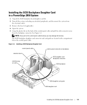
... system configuration. Processor Upgrade Installation Guide 7 See your Installation and Troubleshooting Guide for instructions about running the diagnostics and troubleshooting processor problems. 18 Replace the bezel (if applicable). See "Running the System Diagnostics" in the System Setup program. 16 Press to their electrical outlets, and turn them on.
... system configuration. Processor Upgrade Installation Guide 7 See your Installation and Troubleshooting Guide for instructions about running the diagnostics and troubleshooting processor problems. 18 Replace the bezel (if applicable). See "Running the System Diagnostics" in the System Setup program. 16 Press to their electrical outlets, and turn them on.
Activating the Integrated RAID Controller
Page 5
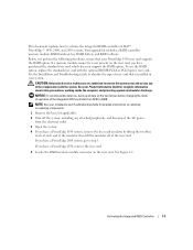
...loss, back up all data on the hard drives before changing the mode of operation of the riser card. Before you have a PowerEdge 1850 system, remove the riser card insulator by lifting the two blue rivets at each end of the insulator, then lift the ... 1 Remove the bezel (if applicable). 2 Turn off of the integrated SCSI controller from the electrical outlet. 3 Open the system. 4 If you have a PowerEdge 2800 system, go to step 5. See Figure 1-1. If you perform the following procedures, ensure that is not present on Dell™ PowerEdge™ 1850, 2800, and 2850 systems....
...loss, back up all data on the hard drives before changing the mode of operation of the riser card. Before you have a PowerEdge 1850 system, remove the riser card insulator by lifting the two blue rivets at each end of the insulator, then lift the ... 1 Remove the bezel (if applicable). 2 Turn off of the integrated SCSI controller from the electrical outlet. 3 Open the system. 4 If you have a PowerEdge 2800 system, go to step 5. See Figure 1-1. If you perform the following procedures, ensure that is not present on Dell™ PowerEdge™ 1850, 2800, and 2850 systems....
Activating the Integrated RAID Controller
Page 8
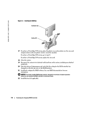
... 21 Install and configure the RAID software. If you can operate the RAID controller in write-back mode. 22 Install the bezel (if applicable). 1-6 Activating the Integrated RAID Controller See your RAID documentation for the SCSI controller has changed to secure the insulator. If... rivets to reflect the presence of system operation before you have a PowerEdge 2800 system, go to step 18. www.dell.com | support.dell.com Figure 1-3. Installing the RAID Key hardware key latches (2) 17 If you have a PowerEdge 1850 system, place the plastic riser card insulator over the riser card...
... 21 Install and configure the RAID software. If you can operate the RAID controller in write-back mode. 22 Install the bezel (if applicable). 1-6 Activating the Integrated RAID Controller See your RAID documentation for the SCSI controller has changed to secure the insulator. If... rivets to reflect the presence of system operation before you have a PowerEdge 2800 system, go to step 18. www.dell.com | support.dell.com Figure 1-3. Installing the RAID Key hardware key latches (2) 17 If you have a PowerEdge 1850 system, place the plastic riser card insulator over the riser card...

Rack- to-Tower Conversion Guide
Page 5
... 6 Before You Begin 6 Installing the Tower-to-Rack Kit 7 Tower-to-Rack Kit Contents 7 Recommended Tools and Supplies 8 Conversion Tasks 8 Removing the Bezel, Metal Feet, and Cover 9 Removing the Control Panel Assembly and Tower Front Panel 12 Installing the Rack Front Panel and Control Panel Assembly 14 Removing...Removing the Rack Doors 17 Installing the System in a Rack 17 Installing the Cable-Management Arm 17 Routing Cables 17 Installing the Rack Bezel 17 Installing the Rack Doors 18 Installing the Rack-to-Tower Kit 18 Rack-to-Tower Kit Contents 18 Before You Begin 20 ...
... 6 Before You Begin 6 Installing the Tower-to-Rack Kit 7 Tower-to-Rack Kit Contents 7 Recommended Tools and Supplies 8 Conversion Tasks 8 Removing the Bezel, Metal Feet, and Cover 9 Removing the Control Panel Assembly and Tower Front Panel 12 Installing the Rack Front Panel and Control Panel Assembly 14 Removing...Removing the Rack Doors 17 Installing the System in a Rack 17 Installing the Cable-Management Arm 17 Routing Cables 17 Installing the Rack Bezel 17 Installing the Rack Doors 18 Installing the Rack-to-Tower Kit 18 Rack-to-Tower Kit Contents 18 Before You Begin 20 ...

Rack- to-Tower Conversion Guide
Page 6
... 13 Removing/Installing the Control Panel Assembly and Front Panel 14 Removing the Trim Panel 16 Installing Shoulder Nuts 17 Installing the Rack Bezel 18 Rack-to-Tower Kit Contents 19 Removing the Cable-Management Arm 21 Removing the System 23 Installing the Tower Trim Panel and ...Metal Feet . . . 24 Installing and Removing the Rack Bezel 25 Removing the System Cover 26 Drive Tray in the Maintenance Position 27 Removing the Rack Control Panel Assembly . . . . 28 Installing the Metal...
... 13 Removing/Installing the Control Panel Assembly and Front Panel 14 Removing the Trim Panel 16 Installing Shoulder Nuts 17 Installing the Rack Bezel 18 Rack-to-Tower Kit Contents 19 Removing the Cable-Management Arm 21 Removing the System 23 Installing the Tower Trim Panel and ...Metal Feet . . . 24 Installing and Removing the Rack Bezel 25 Removing the System Cover 26 Drive Tray in the Maintenance Position 27 Removing the Rack Control Panel Assembly . . . . 28 Installing the Metal...

Rack- to-Tower Conversion Guide
Page 9
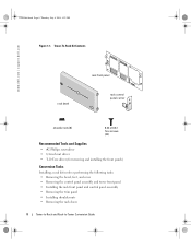
... Figure 1-1): • One rack front panel with rack handles and thumbscrews • Twenty-two 6-32 x 0.312-inch black flat-head Torx screws • One rack bezel, complete with the rack cabinet for instructions on its slide assemblies at one extended system could cause the rack to 49 kilograms (108 pounds) when...
... Figure 1-1): • One rack front panel with rack handles and thumbscrews • Twenty-two 6-32 x 0.312-inch black flat-head Torx screws • One rack bezel, complete with the rack cabinet for instructions on its slide assemblies at one extended system could cause the rack to 49 kilograms (108 pounds) when...
Rack- to-Tower Conversion Guide
Page 10
Tower-To-Rack Kit Contents www.dell.com | support.dell.com rack bezel rack front panel rack control panel carrier shoulder nuts (6) 6-32 x 0.312 Torx screws (22) Recommended Tools and Supplies • #2 Phillips screwdriver • 1/4-inch nut ...• T-10 Torx driver (for removing and installing the front panels) Conversion Tasks Installing a rack kit involves performing the following tasks: • Removing the bezel, feet, and cover • Removing the control panel assembly and tower front panel • Installing the rack front panel and control panel assembly • Removing...
Tower-To-Rack Kit Contents www.dell.com | support.dell.com rack bezel rack front panel rack control panel carrier shoulder nuts (6) 6-32 x 0.312 Torx screws (22) Recommended Tools and Supplies • #2 Phillips screwdriver • 1/4-inch nut ...• T-10 Torx driver (for removing and installing the front panels) Conversion Tasks Installing a rack kit involves performing the following tasks: • Removing the bezel, feet, and cover • Removing the control panel assembly and tower front panel • Installing the rack front panel and control panel assembly • Removing...

Rack- to-Tower Conversion Guide
Page 11
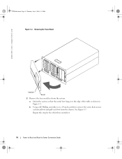
b Rotate the keylock end of the bezel and pull the bezel away from the front panel. See Figure 1-2. c Unhook the other end of the bezel away from the system. Y1001bk0.book Page 9 Thursday, July 8, 2004 4:32 PM • Installing the system in the rack • Installing ...the cable-management arm • Routing cables • Installing the rack bezel • Installing the rack doors Removing the Bezel, Metal Feet, and Cover 1 To remove the bezel, orient the system as shown in Figure 1-2 and perform the following steps: a Unlock the keylock. Tower...
b Rotate the keylock end of the bezel and pull the bezel away from the front panel. See Figure 1-2. c Unhook the other end of the bezel away from the system. Y1001bk0.book Page 9 Thursday, July 8, 2004 4:32 PM • Installing the system in the rack • Installing ...the cable-management arm • Routing cables • Installing the rack bezel • Installing the rack doors Removing the Bezel, Metal Feet, and Cover 1 To remove the bezel, orient the system as shown in Figure 1-2 and perform the following steps: a Unlock the keylock. Tower...
Rack- to-Tower Conversion Guide
Page 12
See Figure 1-3. Removing the Tower Bezel www.dell.com | support.dell.com keylock bezel 2 Remove the four metal feet from the system: a Orient the system so that secures each metal foot and pull each foot from the chassis. Repeat this step for the other three metal feet. 10 Tower-to-Rack and Rack-to-Tower Conversion Guide b Using a #2 Phillips screwdriver or a 1/4-inch nut driver, remove the screw that the metal feet hang over the edge of the table as shown in Figure 1-3. Y1001bk0.book Page 10 Thursday, July 8, 2004 4:32 PM Figure 1-2.
See Figure 1-3. Removing the Tower Bezel www.dell.com | support.dell.com keylock bezel 2 Remove the four metal feet from the system: a Orient the system so that secures each metal foot and pull each foot from the chassis. Repeat this step for the other three metal feet. 10 Tower-to-Rack and Rack-to-Tower Conversion Guide b Using a #2 Phillips screwdriver or a 1/4-inch nut driver, remove the screw that the metal feet hang over the edge of the table as shown in Figure 1-3. Y1001bk0.book Page 10 Thursday, July 8, 2004 4:32 PM Figure 1-2.

Rack- to-Tower Conversion Guide
Page 19
See the documentation provided with the keylock. Secure the bezel with the rack for instructions on removing rack doors. Installing the System in a Rack If you are installing the ... the Cable-Management Arm See the procedures contained in the system Rack Installation Guide. Installing the Rack Bezel To install the bezel, hook the right end of the bezel onto the chassis, then fit the free end of the rack and to prevent damage to the doors...1-8. Routing Cables See the procedures contained in the rack cabinet. Tower-to-Rack and Rack-to the interior of the bezel onto the system.
See the documentation provided with the keylock. Secure the bezel with the rack for instructions on removing rack doors. Installing the System in a Rack If you are installing the ... the Cable-Management Arm See the procedures contained in the system Rack Installation Guide. Installing the Rack Bezel To install the bezel, hook the right end of the bezel onto the chassis, then fit the free end of the rack and to prevent damage to the doors...1-8. Routing Cables See the procedures contained in the rack cabinet. Tower-to-Rack and Rack-to the interior of the bezel onto the system.

Rack- to-Tower Conversion Guide
Page 20
Rack-to-Tower Kit Contents The rack-to -Tower Conversion Guide Installing the Rack Bezel www.dell.com | support.dell.com keylock bezel release latch Installing the Rack Doors See the documentation provided with keylock and keys • One tower front panel 18 Tower-to-Rack ...and Rack-to -tower kit includes the following items (see Figure 1-10): • One tower bezel complete with the rack for ...
Rack-to-Tower Kit Contents The rack-to -Tower Conversion Guide Installing the Rack Bezel www.dell.com | support.dell.com keylock bezel release latch Installing the Rack Doors See the documentation provided with keylock and keys • One tower front panel 18 Tower-to-Rack ...and Rack-to -tower kit includes the following items (see Figure 1-10): • One tower bezel complete with the rack for ...

Rack- to-Tower Conversion Guide
Page 21
Rack-to-Tower Kit Contents tower cover tower trim panel tower front panel tower bezel metal feet (4) tower control panel carrier 8-32 x 0.312 6-32 x 0.312 hex-head Torx screws screws (4) (22) Tower-to-Rack and Rack-to-Tower Conversion Guide 19 Y1001bk0.book Page 19 Thursday, July 8, 2004 4:32 PM • One painted top cover • One tower trim panel • Tower control panel carrier assembly kit • Twenty-two 6-32 x 0.312-inch black flat-head Torx screws Figure 1-10.
Rack-to-Tower Kit Contents tower cover tower trim panel tower front panel tower bezel metal feet (4) tower control panel carrier 8-32 x 0.312 6-32 x 0.312 hex-head Torx screws screws (4) (22) Tower-to-Rack and Rack-to-Tower Conversion Guide 19 Y1001bk0.book Page 19 Thursday, July 8, 2004 4:32 PM • One painted top cover • One tower trim panel • Tower control panel carrier assembly kit • Twenty-two 6-32 x 0.312-inch black flat-head Torx screws Figure 1-10.

Rack- to-Tower Conversion Guide
Page 22
Y1001bk0.book Page 20 Thursday, July 8, 2004 4:32 PM www.dell.com | support.dell.com Before You Begin Before you begin removing your rack cabinet.... tray • Removing the system from the rack • Installing the tower trim panel • Removing the bezel and cover • Removing the rack control panel assembly and rack front panel • Installing the tower front ...panel and tower control panel assembly • Installing the metal feet and bezel • Replacing the rack doors Removing the Rack Doors You must remove the doors from the rack cabinet...
Y1001bk0.book Page 20 Thursday, July 8, 2004 4:32 PM www.dell.com | support.dell.com Before You Begin Before you begin removing your rack cabinet.... tray • Removing the system from the rack • Installing the tower trim panel • Removing the bezel and cover • Removing the rack control panel assembly and rack front panel • Installing the tower front ...panel and tower control panel assembly • Installing the metal feet and bezel • Replacing the rack doors Removing the Rack Doors You must remove the doors from the rack cabinet...


