Microprocessor Upgrade Installation Guide
Page 3
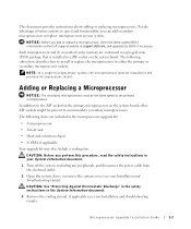
...See "Protecting Against Electrostatic Discharge" in the safety instructions in your System Information document. 1 Turn off the system, including any peripherals, and disconnect the power cable from the electrical outlet. 2 Open the system doors, or remove the system cover (see your Installation and Troubleshooting Guide). Microprocessor Upgrade Installation Guide.... NOTE: In a single microprocessor system, the microprocessor must be present to the ZIF socket for the primary microprocessor on the Dell Support website at support.dell.com, and upgrade the BIOS if necessary.
...See "Protecting Against Electrostatic Discharge" in the safety instructions in your System Information document. 1 Turn off the system, including any peripherals, and disconnect the power cable from the electrical outlet. 2 Open the system doors, or remove the system cover (see your Installation and Troubleshooting Guide). Microprocessor Upgrade Installation Guide.... NOTE: In a single microprocessor system, the microprocessor must be present to the ZIF socket for the primary microprocessor on the Dell Support website at support.dell.com, and upgrade the BIOS if necessary.

Rack Installation Guide
Page 6
... . . 1-11 Installing the System in the Rack (RapidRails or VersaRails 1-12 Installing the Cable-Management Arm . . . 1-14 Installing the Cable-Management Arm . . . 1-15 Routing the Power Cords 1-16 Routing Cables 1-17 Two-Post Rack Kit Components 1-19 Two-Post, Open-Frame Relay Rack Universal-Hole Spacing 1-20 Two-Post, Open-Frame...
... . . 1-11 Installing the System in the Rack (RapidRails or VersaRails 1-12 Installing the Cable-Management Arm . . . 1-14 Installing the Cable-Management Arm . . . 1-15 Routing the Power Cords 1-16 Routing Cables 1-17 Two-Post Rack Kit Components 1-19 Two-Post, Open-Frame Relay Rack Universal-Hole Spacing 1-20 Two-Post, Open-Frame...
Rack Installation Guide
Page 8
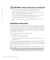
... 6-inch-wide racks) For ease in either center-mount or flush-mount configuration, for installing both RapidRails and VersaRails rack kits are similar. www.dell.com | support.dell.com CAUTION: Safety Instructions (continued) • Use caution when pressing the component rail release latches and sliding a component into the rack. • Do not...
... 6-inch-wide racks) For ease in either center-mount or flush-mount configuration, for installing both RapidRails and VersaRails rack kits are similar. www.dell.com | support.dell.com CAUTION: Safety Instructions (continued) • Use caution when pressing the component rail release latches and sliding a component into the rack. • Do not...

Rack Installation Guide
Page 21
Figure 1-9. Installing the Cable-Management Arm system status indicator cable plug wire covers in open position system status indicator 7 Connect the power cords to their receptacles on the back panel (see Figure 1-10). Rack Installation Guide 1-15
Figure 1-9. Installing the Cable-Management Arm system status indicator cable plug wire covers in open position system status indicator 7 Connect the power cords to their receptacles on the back panel (see Figure 1-10). Rack Installation Guide 1-15

Rack Installation Guide
Page 22
...the middle and one on the system back panel. b Slide the system forward to the front vertical rail. www.dell.com | support.dell.com Figure 1-10. For details on cable connections, see Figure 1-11). c Route the cables along the cable-...management arm, make any adjustments needed to the cablemanagement arm with the tie-wraps, and close the wire covers over the cable-management arm. 1-16 Rack Installation Guide Routing the Power Cords power receptacle housing power...
...the middle and one on the system back panel. b Slide the system forward to the front vertical rail. www.dell.com | support.dell.com Figure 1-10. For details on cable connections, see Figure 1-11). c Route the cables along the cable-...management arm, make any adjustments needed to the cablemanagement arm with the tie-wraps, and close the wire covers over the cable-management arm. 1-16 Rack Installation Guide Routing the Power Cords power receptacle housing power...
Cabling Instructions for the –48 VDC
Page 3
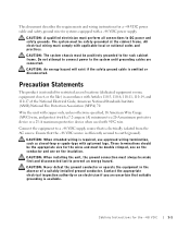
... the system until grounding cables are uncertain that is efficiently secured to prevent an energy hazard. Do not attempt to connect power to the rack cabinet frame. Precaution Statements This product is available. CAUTION: Never defeat the ground conductor or operate the...with copper only, unless otherwise specified, 16 American Wire Gauge (AWG) wire, and protect it with a 7.2-ampere (A) minimum to DC power and safety grounds. Contact the appropriate electrical inspection authority or an electrician if you are connected. CAUTION: A qualified electrician must comply with Articles...
... the system until grounding cables are uncertain that is efficiently secured to prevent an energy hazard. Do not attempt to connect power to the rack cabinet frame. Precaution Statements This product is available. CAUTION: Never defeat the ground conductor or operate the...with copper only, unless otherwise specified, 16 American Wire Gauge (AWG) wire, and protect it with a 7.2-ampere (A) minimum to DC power and safety grounds. Contact the appropriate electrical inspection authority or an electrician if you are connected. CAUTION: A qualified electrician must comply with Articles...
Cabling Instructions for the –48 VDC
Page 4
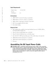
Switch the circuit breaker to the off , locate the circuit breaker on the DC source circuit. www.dell.com | support.dell.com Input Requirements Supply voltage: Current consumption: -(48-60) VDC 8 A Kit Contents • AMP 794949-1 connector housing, or equivalent • AMP 350218-1 ... • Heat-shrink tubing Required Tools • Wire-stripper pliers capable of removing insulation from the DC circuit. To ensure that the power is off position and, if available, install an approved safety locking device to the circuit breaker or switch, to the connector, ensure that the...
Switch the circuit breaker to the off , locate the circuit breaker on the DC source circuit. www.dell.com | support.dell.com Input Requirements Supply voltage: Current consumption: -(48-60) VDC 8 A Kit Contents • AMP 794949-1 connector housing, or equivalent • AMP 350218-1 ... • Heat-shrink tubing Required Tools • Wire-stripper pliers capable of removing insulation from the DC circuit. To ensure that the power is off position and, if available, install an approved safety locking device to the circuit breaker or switch, to the connector, ensure that the...

Cabling Instructions for the –48 VDC
Page 5
..., exposing approximately 4.5 mm (0.175 inches) of copper wire. 2 Using a hand-crimping tool, crimp a connector contact to each DC power wire. 3 Slide a piece of heat-shrink tubing over the DC power cable so that it overlaps the connector housing by at least 6.35 mm (0.25 inches). 7 Using a heat gun, shrink the tubing around... 1-1). 5 Insert the three red -48 VDC return wires into connector housing positions 1, 4, and 5 (see Figure 1-1 and Table 1-1). 6 Slide the heat-shrink tubing over the DC power cable.
..., exposing approximately 4.5 mm (0.175 inches) of copper wire. 2 Using a hand-crimping tool, crimp a connector contact to each DC power wire. 3 Slide a piece of heat-shrink tubing over the DC power cable so that it overlaps the connector housing by at least 6.35 mm (0.25 inches). 7 Using a heat gun, shrink the tubing around... 1-1). 5 Insert the three red -48 VDC return wires into connector housing positions 1, 4, and 5 (see Figure 1-1 and Table 1-1). 6 Slide the heat-shrink tubing over the DC power cable.

Cabling Instructions for the –48 VDC
Page 6
Connecting the -48 VDC Power Cable and Safety Ground 1 Connect the safety ground to the green/yellow wire. Safety Ground safety ground grounding post lock washer #6-32 nut 1-4 Cabling Instructions for the -48 VDC www.dell.com | support.dell.com Assembling the Safety Ground Wire 1 Strip the insulation from the end of the green... ring-tongue terminal to the grounding post on the back of the system using a #6-32 nut equipped with a locking washer (see Figure 1-2). 2 Plug the DC power cable into the system. Figure 1-2.
Connecting the -48 VDC Power Cable and Safety Ground 1 Connect the safety ground to the green/yellow wire. Safety Ground safety ground grounding post lock washer #6-32 nut 1-4 Cabling Instructions for the -48 VDC www.dell.com | support.dell.com Assembling the Safety Ground Wire 1 Strip the insulation from the end of the green... ring-tongue terminal to the grounding post on the back of the system using a #6-32 nut equipped with a locking washer (see Figure 1-2). 2 Plug the DC power cable into the system. Figure 1-2.

2-Post Rack Installation
Page 4
Figure 1-10. Figure 1-8. Figure 1-9. Installing the System Status Indicator Cable Routing the Power Cords Routing Cables 1-14 1-15 1-16 4 Contents
Figure 1-10. Figure 1-8. Figure 1-9. Installing the System Status Indicator Cable Routing the Power Cords Routing Cables 1-14 1-15 1-16 4 Contents
2-Post Rack Installation
Page 6
...the rail into a locking position, and then slide the component into or out of the branch circuit rating. • Ensure that provides power to the rack. This guide includes procedures for the two-post kit (installed in either center-mount or flush-mount configuration, for another... for another system may result in damage to the system and personal injury to yourself and to others. 1-2 2-Post Rack Installation www.dell.com | support.dell.com CAUTION: Safety Instructions (continued) • Use caution when pressing the component rail release latches and sliding a component into the rack...
...the rail into a locking position, and then slide the component into or out of the branch circuit rating. • Ensure that provides power to the rack. This guide includes procedures for the two-post kit (installed in either center-mount or flush-mount configuration, for another... for another system may result in damage to the system and personal injury to yourself and to others. 1-2 2-Post Rack Installation www.dell.com | support.dell.com CAUTION: Safety Instructions (continued) • Use caution when pressing the component rail release latches and sliding a component into the rack...

2-Post Rack Installation
Page 18
Installing the System Status Indicator Cable system status indicator cable plug wire covers in its slot at the back end of the cable-management arm (see Figure 1-9). 1-14 2-Post Rack Installation Figure 1-8. www.dell.com | support.dell.com 6 Route the system status indicator end of the cable through the cable-management arm, and install the indicator in open position system status indicator 7 Connect the power cords to their receptacles on the back panel (see Figure 1-8).
Installing the System Status Indicator Cable system status indicator cable plug wire covers in its slot at the back end of the cable-management arm (see Figure 1-9). 1-14 2-Post Rack Installation Figure 1-8. www.dell.com | support.dell.com 6 Route the system status indicator end of the cable through the cable-management arm, and install the indicator in open position system status indicator 7 Connect the power cords to their receptacles on the back panel (see Figure 1-8).

2-Post Rack Installation
Page 19
... cable slack at this time (see your system's Installation and Troubleshooting Guide and the User's Guide. 2 Route the power and I /O cable connectors to the front vertical rail. Figure 1-9. Routing the Power Cords power receptacle housing power cord plug CAUTION: Allow some cable slack in the middle and one on the system back panel. Routing...
... cable slack at this time (see your system's Installation and Troubleshooting Guide and the User's Guide. 2 Route the power and I /O cable connectors to the front vertical rail. Figure 1-9. Routing the Power Cords power receptacle housing power cord plug CAUTION: Allow some cable slack in the middle and one on the system back panel. Routing...


