Microprocessor Upgrade Installation Guide
Page 3
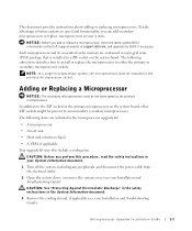
... you add or replace a microprocessor, check the latest system BIOS information on the system board, other ZIF sockets might be installed in your Installation and Troubleshooting Guide). CAUTION: See "Protecting Against Electrostatic Discharge" in the safety instructions in your System Information document. 1 Turn off the system, including any peripherals, and disconnect the power cable from the electrical outlet. 2 Open the system doors, or remove the system cover...
... you add or replace a microprocessor, check the latest system BIOS information on the system board, other ZIF sockets might be installed in your Installation and Troubleshooting Guide). CAUTION: See "Protecting Against Electrostatic Discharge" in the safety instructions in your System Information document. 1 Turn off the system, including any peripherals, and disconnect the power cable from the electrical outlet. 2 Open the system doors, or remove the system cover...
Microprocessor Upgrade Installation Guide
Page 4
... Help" in the open position (see your Installation and Troubleshooting Guide. 1-2 Microprocessor Upgrade Installation Guide Bending the pins can become extremely hot. b Remove the heat sink. Bending the pins can remove the heat sink without removing the fan. www.dell.com | support.dell.com 4 If you can remove the fan to provide easier access to maintain proper thermal conditions. NOTICE: Be careful not to prevent the thermal interface material from being...
... Help" in the open position (see your Installation and Troubleshooting Guide. 1-2 Microprocessor Upgrade Installation Guide Bending the pins can become extremely hot. b Remove the heat sink. Bending the pins can remove the heat sink without removing the fan. www.dell.com | support.dell.com 4 If you can remove the fan to provide easier access to maintain proper thermal conditions. NOTICE: Be careful not to prevent the thermal interface material from being...
Microprocessor Upgrade Installation Guide
Page 5
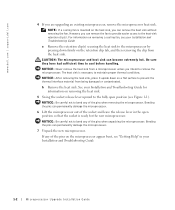
... the microprocessor with pin 1 on the system. Removing and Replacing the Microprocessor pin-1 locators microprocessor microprocessor socket NOTICE: Positioning the microprocessor incorrectly can permanently damage the microprocessor and the system when you turn on the microprocessor socket. a Ensure that all of the microprocessor and socket aligned, set the microprocessor lightly in the socket (see Figure 1-1). c With...
... the microprocessor with pin 1 on the system. Removing and Replacing the Microprocessor pin-1 locators microprocessor microprocessor socket NOTICE: Positioning the microprocessor incorrectly can permanently damage the microprocessor and the system when you turn on the microprocessor socket. a Ensure that all of the microprocessor and socket aligned, set the microprocessor lightly in the socket (see Figure 1-1). c With...
Microprocessor Upgrade Installation Guide
Page 6
... information on installing a cooling fan, see Figure 1-2). c If you received two VRMs with the upgrade kit, replace the primary VRM already installed in your Installation and Troubleshooting Guide. 11 Hook the end of the clip without the release tab over the tab on the edge of the heat sink, remove and discard the cover to expose the thermal grease or foil thermal interface material...
... information on installing a cooling fan, see Figure 1-2). c If you received two VRMs with the upgrade kit, replace the primary VRM already installed in your Installation and Troubleshooting Guide. 11 Hook the end of the clip without the release tab over the tab on the edge of the heat sink, remove and discard the cover to expose the thermal grease or foil thermal interface material...
Microprocessor Upgrade Installation Guide
Page 7
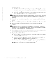
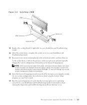
... the System Setup program. Figure 1-2. Installing a VRM VRM VRM connector connector key latches (2) 15 Replace the cooling shroud, if applicable (see your Installation and Troubleshooting Guide). 16 Close the system doors, or replace the system cover (see your system and peripherals to be displayed at the next system startup. Microprocessor Upgrade Installation Guide 1-5 As the system boots, it detects the presence of the system, the chassis intrusion detector...
... the System Setup program. Figure 1-2. Installing a VRM VRM VRM connector connector key latches (2) 15 Replace the cooling shroud, if applicable (see your Installation and Troubleshooting Guide). 16 Close the system doors, or replace the system cover (see your system and peripherals to be displayed at the next system startup. Microprocessor Upgrade Installation Guide 1-5 As the system boots, it detects the presence of the system, the chassis intrusion detector...
Information Update
Page 3
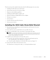
This document provides updated information about the following topics for your system: • Installing the SCSI cable strain-relief bracket • System board connectors for memory modules • Expansion card installation guidelines • Installing the SCSI backplane daughter card • Broadcom NetXtreme Gigabit Ethernet Server Adapter • Microprocessor features • System features • Console redirection special key functions • System memory features Installing the SCSI Cable Strain-Relief Bracket 1 Turn off the system, including any attached...
This document provides updated information about the following topics for your system: • Installing the SCSI cable strain-relief bracket • System board connectors for memory modules • Expansion card installation guidelines • Installing the SCSI backplane daughter card • Broadcom NetXtreme Gigabit Ethernet Server Adapter • Microprocessor features • System features • Console redirection special key functions • System memory features Installing the SCSI Cable Strain-Relief Bracket 1 Turn off the system, including any attached...
Information Update
Page 6
... different operating speeds on LAN (WOL) is connected to a 10/100/1000 link partner in a 2/3 split configuration, you must use the NIC 1 connector. It is recommended that bus. Installing the SCSI Backplane Daughter Card NOTICE: Before installing a SCSI backplane daughter card, back up your system's connection speed is installed and wake on the same bus; Broadcom NetXtreme Gigabit Ethernet Server Adapter When a Broadcom NetXtreme Gigabit Ethernet Server Adapter is 10/100-Mbps. To operate the SCSI backplane in autonegotiation mode...
... different operating speeds on LAN (WOL) is connected to a 10/100/1000 link partner in a 2/3 split configuration, you must use the NIC 1 connector. It is recommended that bus. Installing the SCSI Backplane Daughter Card NOTICE: Before installing a SCSI backplane daughter card, back up your system's connection speed is installed and wake on the same bus; Broadcom NetXtreme Gigabit Ethernet Server Adapter When a Broadcom NetXtreme Gigabit Ethernet Server Adapter is 10/100-Mbps. To operate the SCSI backplane in autonegotiation mode...
Information Update
Page 7
... performance. Information Update 1-5 Microprocessor Features The Intel® Xeon™ microprocessors in the system (speed, cache size, and others.). After the microprocessor information is displayed, you can enable or disable HyperThreading by changing the setting of the Logical Processor option. (The default is Enabled.) You can be executed simultaneously by the system The CPU Information option in the System Setup program's main...
... performance. Information Update 1-5 Microprocessor Features The Intel® Xeon™ microprocessors in the system (speed, cache size, and others.). After the microprocessor information is displayed, you can enable or disable HyperThreading by changing the setting of the Logical Processor option. (The default is Enabled.) You can be executed simultaneously by the system The CPU Information option in the System Setup program's main...
Information Update
Page 8
... type. 1-6 Information Update One or more information about the System Setup program, see "Console Redirection" in the System Setup program. This failover occurs without the need to the number of populated memory banks and whether identical memory modules are of the same type and size. For additional information on console redirection and configuring special key functions, see your User's Guide. NOTE: ANSI escape-sequence key combinations listed...
... type. 1-6 Information Update One or more information about the System Setup program, see "Console Redirection" in the System Setup program. This failover occurs without the need to the number of populated memory banks and whether identical memory modules are of the same type and size. For additional information on console redirection and configuring special key functions, see your User's Guide. NOTE: ANSI escape-sequence key combinations listed...

Rack Installation Guide
Page 5
...: Safety Instructions 1-1 Rack Mounting of Systems 1-1 Installation Instructions 1-2 Four-Post Rack Installation 1-3 Before You Begin 1-3 Recommended Tools and Supplies 1-4 RapidRails Rack Kit Contents 1-4 VersaRails Rack Kit Contents 1-5 Installation Tasks 1-5 Removing the Rack Doors 1-6 Marking the Rack 1-6 Installing the RapidRails Slide Assemblies 1-8 Installing the VersaRails Slide Assemblies 1-10 Installing the System in the Rack 1-11 Installing the Cable-Management Arm 1-13 Routing Cables 1-16 Replacing the Rack Doors 1-17 Two-Post Rack Installation Two-Post Rack...
...: Safety Instructions 1-1 Rack Mounting of Systems 1-1 Installation Instructions 1-2 Four-Post Rack Installation 1-3 Before You Begin 1-3 Recommended Tools and Supplies 1-4 RapidRails Rack Kit Contents 1-4 VersaRails Rack Kit Contents 1-5 Installation Tasks 1-5 Removing the Rack Doors 1-6 Marking the Rack 1-6 Installing the RapidRails Slide Assemblies 1-8 Installing the VersaRails Slide Assemblies 1-10 Installing the System in the Rack 1-11 Installing the Cable-Management Arm 1-13 Routing Cables 1-16 Replacing the Rack Doors 1-17 Two-Post Rack Installation Two-Post Rack...

Rack Installation Guide
Page 6
... Rack Kit Contents 1-4 VersaRails Rack Kit Contents 1-5 One Rack Unit 1-7 Marking the Vertical Rails 1-8 Installing the RapidRails Slide Assemblies . . . 1-9 Installing the VersaRails Slide Assemblies . . 1-11 Installing the System in the Rack (RapidRails or VersaRails 1-12 Installing the Cable-Management Arm . . . 1-14 Installing the Cable-Management Arm . . . 1-15 Routing the Power Cords 1-16 Routing Cables 1-17 Two-Post Rack Kit Components 1-19 Two-Post, Open-Frame Relay Rack Universal-Hole Spacing 1-20 Two-Post, Open-Frame Relay Rack...
... Rack Kit Contents 1-4 VersaRails Rack Kit Contents 1-5 One Rack Unit 1-7 Marking the Vertical Rails 1-8 Installing the RapidRails Slide Assemblies . . . 1-9 Installing the VersaRails Slide Assemblies . . 1-11 Installing the System in the Rack (RapidRails or VersaRails 1-12 Installing the Cable-Management Arm . . . 1-14 Installing the Cable-Management Arm . . . 1-15 Routing the Power Cords 1-16 Routing Cables 1-17 Two-Post Rack Kit Components 1-19 Two-Post, Open-Frame Relay Rack Universal-Hole Spacing 1-20 Two-Post, Open-Frame Relay Rack...
Rack Installation Guide
Page 7
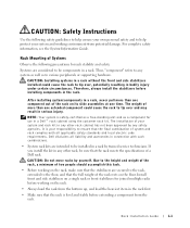
.... CAUTION: Safety Instructions Use the following precautions for rack stability and safety. Rack Mounting of a Dell rack. Dell disclaims all applicable safety standards and local electric code requirements. CAUTION: Installing systems in the rack. It is level and stable before installing components in a rack without the front and side stabilizers installed could cause the rack to the floor, and that the rack meets the specifications of Systems Observe...
.... CAUTION: Safety Instructions Use the following precautions for rack stability and safety. Rack Mounting of a Dell rack. Dell disclaims all applicable safety standards and local electric code requirements. CAUTION: Installing systems in the rack. It is level and stable before installing components in a rack without the front and side stabilizers installed could cause the rack to the floor, and that the rack meets the specifications of Systems Observe...
Rack Installation Guide
Page 8
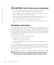
... flush-mount configuration, for another system. CAUTION: Do not install rack kit components designed for trained service technicians installing one or more information on these rack kits include a status-indicator cable that proper airflow is inserted into the rack, carefully extend the rail into a locking position, and then slide the component into or out of the cable-management arm. the slide rails can be installed in a rack. Using the rack kit...
... flush-mount configuration, for another system. CAUTION: Do not install rack kit components designed for trained service technicians installing one or more information on these rack kits include a status-indicator cable that proper airflow is inserted into the rack, carefully extend the rail into a locking position, and then slide the component into or out of the cable-management arm. the slide rails can be installed in a rack. Using the rack kit...
Rack Installation Guide
Page 11
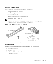
VersaRails Rack Kit Contents The VersaRails rack kit includes the following tasks in their numbered order: 1 Removing the rack doors 2 Marking the rack 3 Installing the slide assemblies in procedural steps are identified by size and number of threads per inch is identified as a 10-32 screw. VersaRails Rack Kit Contents slide assemblies (2) cable-management arm 10-32 x 0.5-inch flange-head Phillips screw (8) status indicator cable Installation Tasks Installing a rack kit involves...
VersaRails Rack Kit Contents The VersaRails rack kit includes the following tasks in their numbered order: 1 Removing the rack doors 2 Marking the rack 3 Installing the slide assemblies in procedural steps are identified by size and number of threads per inch is identified as a 10-32 screw. VersaRails Rack Kit Contents slide assemblies (2) cable-management arm 10-32 x 0.5-inch flange-head Phillips screw (8) status indicator cable Installation Tasks Installing a rack kit involves...
Rack Installation Guide
Page 12
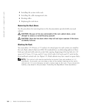
...: The vertical rails may have an alternating pattern of three holes per rack unit with your rack cabinet. www.dell.com | support.dell.com 4 Installing the system in the rack 5 Installing the cable-management arm 6 Routing cables 7 Replacing the rack doors Removing the Rack Doors See the procedures for removing doors in 1-U increments. CAUTION: Because of the size and weight of the number marking on the rack. If you wish...
...: The vertical rails may have an alternating pattern of three holes per rack unit with your rack cabinet. www.dell.com | support.dell.com 4 Installing the system in the rack 5 Installing the cable-management arm 6 Routing cables 7 Replacing the rack doors Removing the Rack Doors See the procedures for removing doors in 1-U increments. CAUTION: Because of the size and weight of the number marking on the rack. If you wish...

Removing and Replacing a System Cooling Fan
Page 2
Removing and Replacing the Cover thumbscrews (3) Figure 2. Removing and Installing a Cooling Fan system fans (2) fan connector cooling fan www.dell.com | support.dell.com Figure 1.
Removing and Replacing the Cover thumbscrews (3) Figure 2. Removing and Installing a Cooling Fan system fans (2) fan connector cooling fan www.dell.com | support.dell.com Figure 1.
Removing and Replacing a System Cooling Fan
Page 3
... system. See Figure 2. 2 Replace the cover. a Align the cover with the cover alignment hooks on the sides of the chassis, and slide the cover forward. Information in the U.S.A. Printed in this document is strictly forbidden. Dell Computer Corporation disclaims any proprietary interest in this text: Dell and the DELL logo are authorized to remove the system cover and access any manner whatsoever without...
... system. See Figure 2. 2 Replace the cover. a Align the cover with the cover alignment hooks on the sides of the chassis, and slide the cover forward. Information in the U.S.A. Printed in this document is strictly forbidden. Dell Computer Corporation disclaims any proprietary interest in this text: Dell and the DELL logo are authorized to remove the system cover and access any manner whatsoever without...
Cabling Instructions for the –48 VDC
Page 4
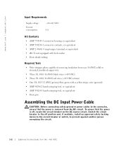
... Heat-shrink tubing Required Tools • Wire-stripper pliers capable of removing insulation from the DC circuit. www.dell.com | support.dell.com Input Requirements Supply voltage: Current consumption: -(48-60) VDC 8 A Kit Contents • AMP 794949-1 connector housing, or equivalent • AMP 350218-1 connector... • Heat gun Assembling the DC Input Power Cable CAUTION: Before connecting safety ground or power cables to prevent against another person energizing the circuit. 1-2 Cabling Instructions for the -48 VDC Switch the circuit breaker to the off , locate the circuit ...
... Heat-shrink tubing Required Tools • Wire-stripper pliers capable of removing insulation from the DC circuit. www.dell.com | support.dell.com Input Requirements Supply voltage: Current consumption: -(48-60) VDC 8 A Kit Contents • AMP 794949-1 connector housing, or equivalent • AMP 350218-1 connector... • Heat gun Assembling the DC Input Power Cable CAUTION: Before connecting safety ground or power cables to prevent against another person energizing the circuit. 1-2 Cabling Instructions for the -48 VDC Switch the circuit breaker to the off , locate the circuit ...

2-Post Rack Installation
Page 3
... Rack Universal-Hole Spacing 1-5 Two-Post, Open-Frame Relay Rack Wide-Hole Spacing 1-5 Installing the Slide Assemblies for Center-Mount Configuration 1-8 Rotating the Front Mounting Bracket for Flush-Mount Installation 1-10 Installing the Slide Assemblies for Flush-Mount Configuration 1-11 Installing the Cable-Management Arm . . . . 1-13 Contents 3 Figure 1-2. Contents CAUTION: Safety Instructions 1-1 Rack Mounting of Systems 1-1 Installation Instructions 1-2 Two-Post Rack Installation 1-3 Recommended Tools and Supplies 1-3 Rack Kit Contents 1-3 Two-Post Rack Installation...
... Rack Universal-Hole Spacing 1-5 Two-Post, Open-Frame Relay Rack Wide-Hole Spacing 1-5 Installing the Slide Assemblies for Center-Mount Configuration 1-8 Rotating the Front Mounting Bracket for Flush-Mount Installation 1-10 Installing the Slide Assemblies for Flush-Mount Configuration 1-11 Installing the Cable-Management Arm . . . . 1-13 Contents 3 Figure 1-2. Contents CAUTION: Safety Instructions 1-1 Rack Mounting of Systems 1-1 Installation Instructions 1-2 Two-Post Rack Installation 1-3 Recommended Tools and Supplies 1-3 Rack Kit Contents 1-3 Two-Post Rack Installation...
2-Post Rack Installation
Page 6
Installation Instructions This installation guide provides instructions for another system. This guide includes procedures for the two-post kit (installed in either center-mount or flush-mount configuration, for your system. Use only the rack kit for 3- Using the rack kit for trained service technicians installing one or more information on these indicators, see your fingers. • After a component is inserted into the rack, carefully extend the rail into a locking position, and then...
Installation Instructions This installation guide provides instructions for another system. This guide includes procedures for the two-post kit (installed in either center-mount or flush-mount configuration, for your system. Use only the rack kit for 3- Using the rack kit for trained service technicians installing one or more information on these indicators, see your fingers. • After a component is inserted into the rack, carefully extend the rail into a locking position, and then...


