
Information Update
Page 3
... Monitoring Features 5 New I/O and Storage Features 6 New Security Features 6 Optional Internal USB Memory Key 6 Installing the Optional Internal USB Memory Key . . 8 Support for 8-GB Memory Modules - PowerEdge 1950 II and PowerEdge 1950 III Systems 9 System Board Replacement - PowerEdge 1950 III Systems 9 Processor Upgrades - Contents Non-Optimal Memory Configurations 5 PowerEdge 1950 III - Safeguarding Encrypted Data 10 System Message Update 10 LCD Status Messages Update...
... Monitoring Features 5 New I/O and Storage Features 6 New Security Features 6 Optional Internal USB Memory Key 6 Installing the Optional Internal USB Memory Key . . 8 Support for 8-GB Memory Modules - PowerEdge 1950 II and PowerEdge 1950 III Systems 9 System Board Replacement - PowerEdge 1950 III Systems 9 Processor Upgrades - Contents Non-Optimal Memory Configurations 5 PowerEdge 1950 III - Safeguarding Encrypted Data 10 System Message Update 10 LCD Status Messages Update...
Information Update
Page 4
Incorrect Processor Information 25 System Support for Microsoft Windows 2000 . . . 25 Hardware Owner's Manual Updates 26 Installing the Processor 26 System Diagnostics Custom Test Options . . . . . 26 4 Contents System Setup Program Update 21 Memory Screen 21 CPU Information Screen 22 Integrated Devices Screen 22 System Security Screen 23 Operating System Information 25 Enumeration of NICs 25 RHEL -
Incorrect Processor Information 25 System Support for Microsoft Windows 2000 . . . 25 Hardware Owner's Manual Updates 26 Installing the Processor 26 System Diagnostics Custom Test Options . . . . . 26 4 Contents System Setup Program Update 21 Memory Screen 21 CPU Information Screen 22 Integrated Devices Screen 22 System Security Screen 23 Operating System Information 25 Enumeration of NICs 25 RHEL -
Information Update
Page 8
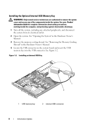
... Hardware Owner's Manual. 4 Locate the USB connector on the system board and insert the USB memory key into the USB connector. Installing an Internal USB Key 1 2 1 USB memory key 2 internal USB connector 8 Information Update See your Product Information Guide for complete information about ... and protecting against electrostatic discharge. 1 Turn off the system, including any of the components inside the system. Installing the Optional Internal USB Memory Key WARNING: Only trained service technicians are authorized to remove the system cover and access any attached peripherals, and ...
... Hardware Owner's Manual. 4 Locate the USB connector on the system board and insert the USB memory key into the USB connector. Installing an Internal USB Key 1 2 1 USB memory key 2 internal USB connector 8 Information Update See your Product Information Guide for complete information about ... and protecting against electrostatic discharge. 1 Turn off the system, including any of the components inside the system. Installing the Optional Internal USB Memory Key WARNING: Only trained service technicians are authorized to remove the system cover and access any attached peripherals, and ...
Information Update
Page 9
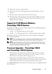
...front of your system chassis is labeled with a "II," your system is labeled with your system. PowerEdge 1950 III Systems PowerEdge 1950 III systems have added support for information on memory support requirements and restrictions, refer to power and restart the system. 8 Enter the System Setup program...that the latest system BIOS version is on your system is installed, the system only recognizes and displays 63.75 GB during POST. See support.dell.com for the following approved 8-GB memory configurations: • 64 GB - 8 x 8-GB quad-rank memory modules • 48 GB - 4 x 8-GB quad-...
...front of your system chassis is labeled with a "II," your system is labeled with your system. PowerEdge 1950 III Systems PowerEdge 1950 III systems have added support for information on memory support requirements and restrictions, refer to power and restart the system. 8 Enter the System Setup program...that the latest system BIOS version is on your system is installed, the system only recognizes and displays 63.75 GB during POST. See support.dell.com for the following approved 8-GB memory configurations: • 64 GB - 8 x 8-GB quad-rank memory modules • 48 GB - 4 x 8-GB quad-...
Information Update
Page 11
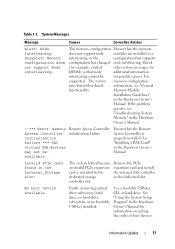
... Alert! Check (for example, a failed other system messages for DIMM) so that supports configuration has changed node interleaving. Memory Module Installation Guidelines" in the Internal_Storage slot! Invalid PCIe card found in the Hardware Owner's Manual. See "Using the System Setup...Faulty or missing optical drive subsystem, hard drive, or hard-drive subsystem, or no bootable USB key installed. Information Update 11 Memory configuration does not support Node Interleaving. For supported. Remote Access Controller initialization failure. The system halted because ...
... Alert! Check (for example, a failed other system messages for DIMM) so that supports configuration has changed node interleaving. Memory Module Installation Guidelines" in the Internal_Storage slot! Invalid PCIe card found in the Hardware Owner's Manual. See "Using the System Setup...Faulty or missing optical drive subsystem, hard drive, or hard-drive subsystem, or no bootable USB key installed. Information Update 11 Memory configuration does not support Node Interleaving. For supported. Remote Access Controller initialization failure. The system halted because ...
Information Update
Page 15
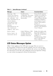
.... For hard drive problems, see the system documentation on the PowerEdge 1950 III system and the probable cause for each message. Information Update 15 The LCD messages refer to the LCD status messages that the memory modules are installed in the Hardware Owner's Manual. Invalid memory configuration. Reseat the USB device or USB cable. System...
.... For hard drive problems, see the system documentation on the PowerEdge 1950 III system and the probable cause for each message. Information Update 15 The LCD messages refer to the LCD status messages that the memory modules are installed in the Hardware Owner's Manual. Invalid memory configuration. Reseat the USB device or USB cable. System...
Information Update
Page 21
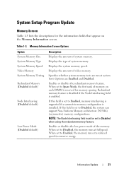
... at full speed. If this field is installed. NOTE: The Node Interleaving field must be set to Enabled, memory interleaving is supported if a symmetric memory configuration is set to Enabled, the memory runs at a reduced speed to Disabled, the system can support Non-Uniform Memory architecture (NUMA) (asymmetric) memory configurations. When set to conserve energy. Displays...
... at full speed. If this field is installed. NOTE: The Node Interleaving field must be set to Enabled, memory interleaving is supported if a symmetric memory configuration is set to Enabled, the memory runs at a reduced speed to Disabled, the system can support Non-Uniform Memory architecture (NUMA) (asymmetric) memory configurations. When set to conserve energy. Displays...

Information Update
Page 26
You cannot save the file to specify the diskette drive or USB memory key where the test log file is saved. System Diagnostics Custom Test Options In the Customize window of the system diagnostics, the Log output file pathname option enables you to a hard drive. 26 Information Update Hardware Owner's Manual Updates Installing the Processor When installing the processor, the processor shield must be closed before securing the processor with the socket release lever.
You cannot save the file to specify the diskette drive or USB memory key where the test log file is saved. System Diagnostics Custom Test Options In the Customize window of the system diagnostics, the Log output file pathname option enables you to a hard drive. 26 Information Update Hardware Owner's Manual Updates Installing the Processor When installing the processor, the processor shield must be closed before securing the processor with the socket release lever.
Information Update
Page 40
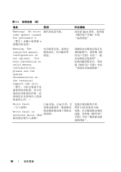
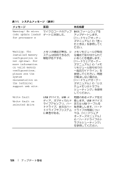
For more information on valid memory configurations, please see the system documentation on the technical support web site Write fault USB 设备、USB Write fault on selected drive USB 设备或 USB 40 信息更新 表 1-1 信息 原因 纠正措施 Warning! No micro code update loaded for processor n n 请更新 BIOS Warning: The installed memory configuration is not optimal.
For more information on valid memory configurations, please see the system documentation on the technical support web site Write fault USB 设备、USB Write fault on selected drive USB 设备或 USB 40 信息更新 表 1-1 信息 原因 纠正措施 Warning! No micro code update loaded for processor n n 请更新 BIOS Warning: The installed memory configuration is not optimal.
Information Update
Page 126
For more information on valid memory configurations, please see the system documentation on selected drive USB USB USB USB 126 No micro code update loaded for processor n BIOS ださい。 Warning: The installed memory configuration is not optimal. 表 1-1 原因 対応処置 Warning! Write fault Write fault on the technical support web site.
For more information on valid memory configurations, please see the system documentation on selected drive USB USB USB USB 126 No micro code update loaded for processor n BIOS ださい。 Warning: The installed memory configuration is not optimal. 表 1-1 原因 対応処置 Warning! Write fault Write fault on the technical support web site.
Information Update
Page 152
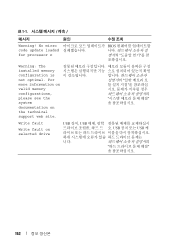
표 1-1 메시지 원인 Warning! No micro code update loaded for processor n BIOS Warning: The installed memory configuration is not optimal. For more information on valid memory configurations, please see the system documentation on selected drive USB 장치, USB USB USB 케 니다. 152 Write fault Write fault on the technical support web site.
표 1-1 메시지 원인 Warning! No micro code update loaded for processor n BIOS Warning: The installed memory configuration is not optimal. For more information on valid memory configurations, please see the system documentation on selected drive USB 장치, USB USB USB 케 니다. 152 Write fault Write fault on the technical support web site.
Hardware Owner's Manual (PDF)
Page 4
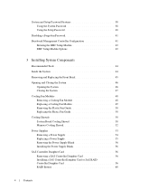
...40 Disabling a Forgotten Password 41 Baseboard Management Controller Configuration 41 Entering the BMC Setup Module 42 BMC Setup Module Options 42 3 Installing System Components Recommended Tools 44 Inside the System 44 Removing and Replacing the Front Bezel 45 Opening and Closing the System 46 ... Plastic Fan Guide 50 Cooling Shrouds 50 System Board Cooling Shroud 50 Memory Cooling Shroud 52 Power Supplies 53 Removing a Power Supply 54 Replacing a Power Supply 55 Removing the Power Supply Blank 56 Installing the Power Supply Blank 56 SAS Controller Daughter Card 56 Removing a ...
...40 Disabling a Forgotten Password 41 Baseboard Management Controller Configuration 41 Entering the BMC Setup Module 42 BMC Setup Module Options 42 3 Installing System Components Recommended Tools 44 Inside the System 44 Removing and Replacing the Front Bezel 45 Opening and Closing the System 46 ... Plastic Fan Guide 50 Cooling Shrouds 50 System Board Cooling Shroud 50 Memory Cooling Shroud 52 Power Supplies 53 Removing a Power Supply 54 Replacing a Power Supply 55 Removing the Power Supply Blank 56 Installing the Power Supply Blank 56 SAS Controller Daughter Card 56 Removing a ...

Hardware Owner's Manual (PDF)
Page 5
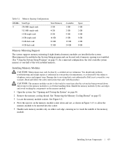
... Card 61 Removing an Expansion Card 62 Configuring the Boot Device 63 Configuring the Boot Drive 63 System Memory 63 General Memory Module Installation Guidelines 64 Non-Optimal Memory Configurations 64 Memory Sparing Support 64 Memory Mirroring Support 65 Installing Memory Modules 65 Removing Memory Modules 67 Activating the Integrated NIC TOE 67 Processors 67 Removing the Processor 67...
... Card 61 Removing an Expansion Card 62 Configuring the Boot Device 63 Configuring the Boot Drive 63 System Memory 63 General Memory Module Installation Guidelines 64 Non-Optimal Memory Configurations 64 Memory Sparing Support 64 Memory Mirroring Support 65 Installing Memory Modules 65 Removing Memory Modules 67 Activating the Integrated NIC TOE 67 Processors 67 Removing the Processor 67...
Hardware Owner's Manual (PDF)
Page 25
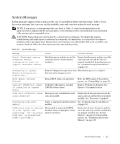
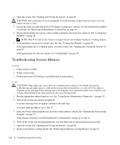
... and that is not covered by your product documentation, or as directed by Dell is running when the message appears or the operating system's documentation for each message. Mismatched or unmatched DIMMs installed; If the problem persists, see "Troubleshooting System Memory" on page 63. Table 1-8 lists the system messages that came with different...
... and that is not covered by your product documentation, or as directed by Dell is running when the message appears or the operating system's documentation for each message. Mismatched or unmatched DIMMs installed; If the problem persists, see "Troubleshooting System Memory" on page 63. Table 1-8 lists the system messages that came with different...
Hardware Owner's Manual (PDF)
Page 65
...by a certified service technician. Read and follow the safety instructions that is not authorized by Dell is one-half of the memory module. See Figure 6-2. 4 Press the ejectors on the memory module socket down and out, as directed by the card edges and avoid touching the ...components on either card edge, ensuring not to the touch for the memory modules to servicing that came with the product. Handle the memory modules by the online or telephone service and support team. Installing Memory Modules CAUTION: Many repairs may only be done by your product documentation,...
...by a certified service technician. Read and follow the safety instructions that is not authorized by Dell is one-half of the memory module. See Figure 6-2. 4 Press the ejectors on the memory module socket down and out, as directed by the card edges and avoid touching the ...components on either card edge, ensuring not to the touch for the memory modules to servicing that came with the product. Handle the memory modules by the online or telephone service and support team. Installing Memory Modules CAUTION: Many repairs may only be done by your product documentation,...
Hardware Owner's Manual (PDF)
Page 102
... Help" on the system and attached peripherals. For the identification number of memory installed matches the system memory setting, go to the fan power connector. Action CAUTION: Many repairs may only be done by Dell is not resolved, install a new fan. See "Using Server Administrator Diagnostics" on page 111. ...online or telephone service and support team. If the replacement fan does not operate, see "Removing and Installing a Cooling Fan" on page 49. 4 Ensure that came with system memory. Damage due to the next step. See "Opening and Closing the System" on page 31. See ...
... Help" on the system and attached peripherals. For the identification number of memory installed matches the system memory setting, go to the fan power connector. Action CAUTION: Many repairs may only be done by Dell is not resolved, install a new fan. See "Using Server Administrator Diagnostics" on page 111. ...online or telephone service and support team. If the replacement fan does not operate, see "Removing and Installing a Cooling Fan" on page 49. 4 Ensure that came with system memory. Damage due to the next step. See "Opening and Closing the System" on page 31. See ...
Hardware Owner's Manual (PDF)
Page 103
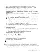
... configurations for each memory module installed. c Swap the memory module in an optical drive. • Optical drive indicator does not blink during boot. NOTE: DVD devices are data only. See "Opening and Closing the System" on page 31. Read and follow the safety instructions that is not authorized by Dell is not covered by...
... configurations for each memory module installed. c Swap the memory module in an optical drive. • Optical drive indicator does not blink during boot. NOTE: DVD devices are data only. See "Opening and Closing the System" on page 31. Read and follow the safety instructions that is not authorized by Dell is not covered by...
Hardware Owner's Manual (PDF)
Page 153
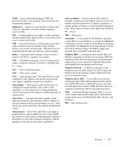
...be integrated into the system board or may need to match the video adapter installed in a business or home to your system's video capabilities. video memory - Most VGA and SVGA video adapters include memory chips in the C programming language. To display a program at a chosen ...data to other hubs or switches without requiring a crossover cable. Windows Server 2003 - Volt(s) direct current. The amount of video memory installed primarily influences the number of use on the hard drive. video resolution - A set of Microsoft software technologies that provides advanced operating...
...be integrated into the system board or may need to match the video adapter installed in a business or home to your system's video capabilities. video memory - Most VGA and SVGA video adapters include memory chips in the C programming language. To display a program at a chosen ...data to other hubs or switches without requiring a crossover cable. Windows Server 2003 - Volt(s) direct current. The amount of video memory installed primarily influences the number of use on the hard drive. video resolution - A set of Microsoft software technologies that provides advanced operating...
Hardware Owner's Manual (PDF)
Page 156
... features back-panel, 14 front-panel, 11 front panel features, 11 fully buffered DIMMs memory modules, 63 G guidelines expansion card installation, 61 guidelines for memory installation, 64 H hard drive installing SAS in a SATAu drive carrier, 78 installing SATA in a SATA drive carrier, 79 installing SATA in a SATAu drive carrier, 80 removing from a drive carrier, 78 hard drives...
... features back-panel, 14 front-panel, 11 front panel features, 11 fully buffered DIMMs memory modules, 63 G guidelines expansion card installation, 61 guidelines for memory installation, 64 H hard drive installing SAS in a SATAu drive carrier, 78 installing SATA in a SATA drive carrier, 79 installing SATA in a SATAu drive carrier, 80 removing from a drive carrier, 78 hard drives...
Hardware Owner's Manual (PDF)
Page 157
troubleshooting, 95 M memory installation guidelines, 64 installing, 65 system, 63 troubleshooting, 102 memory cooling shroud, 52 removing, 52 replacing, 53 memory module sockets, 63 memory modules removing, 67 messages alert, 30 diagnostics, 30 error messages, 31 hard-drive indicator codes, 12 status LCD, 17 system, 25 warning, 30 microprocessors troubleshooting, ...
troubleshooting, 95 M memory installation guidelines, 64 installing, 65 system, 63 troubleshooting, 102 memory cooling shroud, 52 removing, 52 replacing, 53 memory module sockets, 63 memory modules removing, 67 messages alert, 30 diagnostics, 30 error messages, 31 hard-drive indicator codes, 12 status LCD, 17 system, 25 warning, 30 microprocessors troubleshooting, ...


