

Getting Started Guide
Page 5
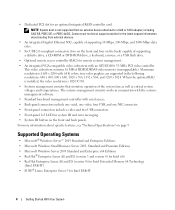
...inch, internal Serial-Attached SCSI (SAS) hard drives or six 3.5-inch, internal SATA hard drives. • Peripheral bay provides support for up to x8 expansion cards. SMP greatly improves overall system performance by installing combinations of the Intel Xeon processor will work properly... as additional processors. The upgrade kit from Dell. slot 3 is available on the system board. • Support for an optional optical drive and an optional half-height tape backup unit (TBU). • An optional...
...inch, internal Serial-Attached SCSI (SAS) hard drives or six 3.5-inch, internal SATA hard drives. • Peripheral bay provides support for up to x8 expansion cards. SMP greatly improves overall system performance by installing combinations of the Intel Xeon processor will work properly... as additional processors. The upgrade kit from Dell. slot 3 is available on the system board. • Support for an optional optical drive and an optional half-height tape backup unit (TBU). • An optional...
Getting Started Guide
Page 6
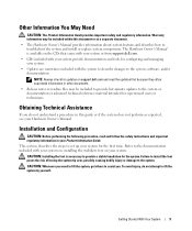
...circuitry works in the following resolutions: 640 x 480, 800 x 600, 1024 x 768, 1152 x 864, and 1280 x 1024. Supported Operating Systems • Microsoft® Windows Server™ 2003 Standard and Enterprise Editions • Microsoft Windows Small Business Server 2003, Standard ...Technology (Intel EM64T) • SUSE® Linux Enterprise Server 9 for an optional integrated RAID controller card. true-color graphics are supported in conjunction with the systems management software. • Standard baseboard management controller with 64 K colors; Maximum resolution is 1600 x 1200...
...circuitry works in the following resolutions: 640 x 480, 800 x 600, 1024 x 768, 1152 x 864, and 1280 x 1024. Supported Operating Systems • Microsoft® Windows Server™ 2003 Standard and Enterprise Editions • Microsoft Windows Small Business Server 2003, Standard ...Technology (Intel EM64T) • SUSE® Linux Enterprise Server 9 for an optional integrated RAID controller card. true-color graphics are supported in conjunction with the systems management software. • Standard baseboard management controller with 64 K colors; Maximum resolution is 1600 x 1200...
Getting Started Guide
Page 7
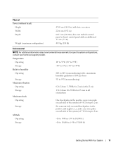
...Always check for experienced users or technicians. CAUTION: Installing the feet is available on the CDs that came with your system or from support.dell.com. • CDs included with the system to describe changes to lift the system by yourself. Getting Started With Your System ...your Product Information Guide. This section describes the steps to the documentation included with your system on installing the stabilizer feet on support.dell.com and read and follow the safety instructions and important regulatory information in other documents. • Release notes or readme ...
...Always check for experienced users or technicians. CAUTION: Installing the feet is available on the CDs that came with your system or from support.dell.com. • CDs included with the system to describe changes to lift the system by yourself. Getting Started With Your System ...your Product Information Guide. This section describes the steps to the documentation included with your system on installing the stabilizer feet on support.dell.com and read and follow the safety instructions and important regulatory information in other documents. • Release notes or readme ...
Getting Started Guide
Page 13
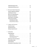
... pulses in the positive and negative x, y, and z axes (one pulse on each side of the system) of 71 G for specific system configurations, contact your technical support provider. Temperature Operating 10° to 35°C (50° to 95°F) Storage -40° to 65°C (-40° to 149°F) Relative...
... pulses in the positive and negative x, y, and z axes (one pulse on each side of the system) of 71 G for specific system configurations, contact your technical support provider. Temperature Operating 10° to 35°C (50° to 95°F) Storage -40° to 65°C (-40° to 149°F) Relative...

Hardware Owner's Manual (PDF)
Page 5
... Fan Bracket 80 Replacing the Back Fan Bracket 80 Memory 80 General Memory Module Installation Guidelines 82 Non-Optimal Memory Configurations 82 Memory Sparing Support 82 Memory Mirroring Support 83 Installing Memory Modules 83 Removing Memory Modules 85 Installing a RAC Card 85 Activating the Integrated NIC TOE 87 Microprocessor 87 Replacing a Processor...
... Fan Bracket 80 Replacing the Back Fan Bracket 80 Memory 80 General Memory Module Installation Guidelines 82 Non-Optimal Memory Configurations 82 Memory Sparing Support 82 Memory Mirroring Support 83 Installing Memory Modules 83 Removing Memory Modules 85 Installing a RAC Card 85 Activating the Integrated NIC TOE 87 Microprocessor 87 Replacing a Processor...
Hardware Owner's Manual (PDF)
Page 7
... System Board Connectors 127 Disabling a Forgotten Password 129 7 Getting Help Technical Assistance 131 Online Services 131 AutoTech Service 132 Automated Order-Status Service 132 Technical Support Service 132 Dell Enterprise Training and Certification 133 Problems With Your Order 133 Product Information 133 Returning Items for Warranty Repair or Credit 133 Contents 7
... System Board Connectors 127 Disabling a Forgotten Password 129 7 Getting Help Technical Assistance 131 Online Services 131 AutoTech Service 132 Automated Order-Status Service 132 Technical Support Service 132 Dell Enterprise Training and Certification 133 Problems With Your Order 133 Product Information 133 Returning Items for Warranty Repair or Credit 133 Contents 7
Hardware Owner's Manual (PDF)
Page 9
... type of message, lists the possible causes, and provides steps to resolve any components you when a problem arises. About Your System 9 The physical connectors on support.dell.com and read the updates first because they often supersede information in this document or as a separate document. • The Getting Started Guide provides an...
... type of message, lists the possible causes, and provides steps to resolve any components you when a problem arises. About Your System 9 The physical connectors on support.dell.com and read the updates first because they often supersede information in this document or as a separate document. • The Getting Started Guide provides an...
Hardware Owner's Manual (PDF)
Page 10
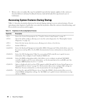
... program. See "Running the System Diagnostics" on page 33. For more information. Option is displayed only if you have the optional Dell Remote Access Controller (DRAC), this keystroke allows access to selected DRAC configuration settings. See the DRAC user's guide for more information, see... Table 1-1 describes keystrokes that may be entered during startup to access system features. Opens the utility partition, allowing you have PXE support enabled through the System Setup Program (see the documentation for your system and try again. See the BMC documentation for more information...
... program. See "Running the System Diagnostics" on page 33. For more information. Option is displayed only if you have the optional Dell Remote Access Controller (DRAC), this keystroke allows access to selected DRAC configuration settings. See the DRAC user's guide for more information, see... Table 1-1 describes keystrokes that may be entered during startup to access system features. Opens the utility partition, allowing you have PXE support enabled through the System Setup Program (see the documentation for your system and try again. See the BMC documentation for more information...

Hardware Owner's Manual (PDF)
Page 12
... button is on indicator lights when the system power is pressed. The power button controls the DC power supply output to do so by qualified support personnel or by descriptive text. Table 1-2. Use this button only if directed to the system.
... button is on indicator lights when the system power is pressed. The power button controls the DC power supply output to do so by qualified support personnel or by descriptive text. Table 1-2. Use this button only if directed to the system.
Hardware Owner's Manual (PDF)
Page 16
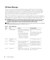
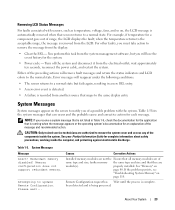
... LCD lights blue to indicate a normal operating condition and lights amber to the components. LCD Status Messages Code Text N/A SYSTEM NAME E1000 E1114 FAILSAFE, Call Support Temp Ambient E1116 Temp Memory E1210 CMOS Batt Causes Corrective Actions A 62-character string that can be This message is for each message. See under...
... LCD lights blue to indicate a normal operating condition and lights amber to the components. LCD Status Messages Code Text N/A SYSTEM NAME E1000 E1114 FAILSAFE, Call Support Temp Ambient E1116 Temp Memory E1210 CMOS Batt Causes Corrective Actions A 62-character string that can be This message is for each message. See under...
Hardware Owner's Manual (PDF)
Page 17
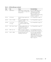
... exceeded the allowable voltage range See "Getting Help" on page 109. Cooling Problems" on page 131. See your system's Information Update Tech Sheet located on support.dell.com for the most current system information.
... exceeded the allowable voltage range See "Getting Help" on page 109. Cooling Problems" on page 131. See your system's Information Update Tech Sheet located on support.dell.com for the most current system information.

Hardware Owner's Manual (PDF)
Page 20
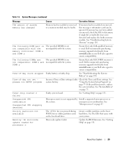
... E2012 E2013 E2014 E2015 E2016 E2017 E2018 E2019 E201A E201B E201C E201D E201E Text Causes Corrective Actions CPU & Firmware Mismatch The BMC firmware does not support the CPU. Prog Timer Programmable interval timer error. Update to copy See "Troubleshooting System its flash image into memory.
... E2012 E2013 E2014 E2015 E2016 E2017 E2018 E2019 E201A E201B E201C E201D E201E Text Causes Corrective Actions CPU & Firmware Mismatch The BMC firmware does not support the CPU. Prog Timer Programmable interval timer error. Update to copy See "Troubleshooting System its flash image into memory.
Hardware Owner's Manual (PDF)
Page 23
... Information Guide for the system. • Power cycle - See "Memory" on page 110. when the temperature returns to the normal state. Memory configuration does not support redundant memory. faulty memory the same type and size and that maps to update Remote Configuration. About Your System 23
... Information Guide for the system. • Power cycle - See "Memory" on page 110. when the temperature returns to the normal state. Memory configuration does not support redundant memory. faulty memory the same type and size and that maps to update Remote Configuration. About Your System 23
Hardware Owner's Manual (PDF)
Page 29
... Install a supported microprocessor or the system. See "Troubleshooting the System Battery" on the boot hard drive. See system battery. Utility partition not available The key was pressed during POST, but no utility partition exists on page 108. See the CDs that only Dell-qualified memory ... compatible with the memory controller: DIMM x and DIMM y The specified DIMM(s) are not compatible: DIMM x and incompatible with your Dell sales agent to determine if single-bit or multi-bit errors were detected and replace the faulty memory module. Time-of -day clock...
... Install a supported microprocessor or the system. See "Troubleshooting the System Battery" on the boot hard drive. See system battery. Utility partition not available The key was pressed during POST, but no utility partition exists on page 108. See the CDs that only Dell-qualified memory ... compatible with the memory controller: DIMM x and DIMM y The specified DIMM(s) are not compatible: DIMM x and incompatible with your Dell sales agent to determine if single-bit or multi-bit errors were detected and replace the faulty memory module. Time-of -day clock...
Hardware Owner's Manual (PDF)
Page 36
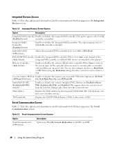
... C: drive in DOS or DOS-like operating systems. USB Flash Drive Type (Auto default) Determines the emulation type for the latest support information about booting from an external device attached to configure the system password and setup password features. PCI IRQ Assignment Displays a screen ... related to the keyboard or keyboard controller during system startup. SATA Port X Displays type and capacity of the integrated devices on ). See support.dell.com for a USB flash drive. Hard disk allows the USB flash drive to Port X on page 38. Auto automatically chooses an emulation...
... C: drive in DOS or DOS-like operating systems. USB Flash Drive Type (Auto default) Determines the emulation type for the latest support information about booting from an external device attached to configure the system password and setup password features. PCI IRQ Assignment Displays a screen ... related to the keyboard or keyboard controller during system startup. SATA Port X Displays type and capacity of the integrated devices on ). See support.dell.com for a USB flash drive. Hard disk allows the USB flash drive to Port X on page 38. Auto automatically chooses an emulation...
Hardware Owner's Manual (PDF)
Page 37
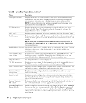
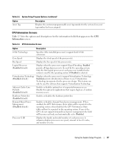
...X ID Displays the family and model number of sequential memory access. Virtualization Technology (Disabled default) Displays when the processor(s) support Virtualization Technology. System Setup Program Options (continued) Option Asset Tag Description Displays the customer-programmable asset tag number for applications ...on the CPU Information screen. Core Speed Displays the clock speed of random memory access. If any of the CPUs do not support demand-based power management, the field will become read-only, and automatically set to be reported to use of each processor installed...
...X ID Displays the family and model number of sequential memory access. Virtualization Technology (Disabled default) Displays when the processor(s) support Virtualization Technology. System Setup Program Options (continued) Option Asset Tag Description Displays the customer-programmable asset tag number for applications ...on the CPU Information screen. Core Speed Displays the clock speed of random memory access. If any of the CPUs do not support demand-based power management, the field will become read-only, and automatically set to be reported to use of each processor installed...
Hardware Owner's Manual (PDF)
Page 38
..., and Off. 38 Using the System Setup Program Embedded Gb NIC (Enabled with PXE, and Disabled. Options are attached to boot from the network. PXE support allows the system to the channel. Changes take effect after the system reboots. MAC Address Displays the MAC address for the integrated 10/100/1000...
..., and Off. 38 Using the System Setup Program Embedded Gb NIC (Enabled with PXE, and Disabled. Options are attached to boot from the network. PXE support allows the system to the channel. Changes take effect after the system reboots. MAC Address Displays the MAC address for the integrated 10/100/1000...
Hardware Owner's Manual (PDF)
Page 40
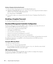
... shipped to you leave your system unlocked so that someone can only turn off after the power button is set to do so by qualified support personnel or by changing a jumper setting. If your data requires more security, use additional forms of security for the data on your system if you...
... shipped to you leave your system unlocked so that someone can only turn off after the power button is set to do so by qualified support personnel or by changing a jumper setting. If your data requires more security, use additional forms of security for the data on your system if you...
Hardware Owner's Manual (PDF)
Page 44
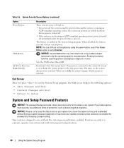
... the setup password window, and press twice to system event log and sensor status • Control of system functions including power on and off • Support is independent of systems remotely.
... the setup password window, and press twice to system event log and sensor status • Control of system functions including power on and off • Support is independent of systems remotely.
Hardware Owner's Manual (PDF)
Page 50
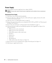
... backup unit • Cable retention clips on page 48. 4 Remove the expansion-bay and processor-cooling fans (FAN1, FAN2, and FAN3). Power Supply Your system supports one power supply rated at an output of 800 W.
... backup unit • Cable retention clips on page 48. 4 Remove the expansion-bay and processor-cooling fans (FAN1, FAN2, and FAN3). Power Supply Your system supports one power supply rated at an output of 800 W.


