

Getting Started Guide
Page 5
...signals the appropriate systems management software if the top cover is a 3.3-V, PCIe x8 lane; NOTE: If you must order the processor upgrade kits from Dell contains the correct version of the processor and heat sink. • A minimum of 512 MB of 256-MB, 512-MB, 1-GB or 2-...sockets on the system board. • Support for up to six 3.5-inch, internal Serial-Attached SCSI (SAS) hard drives or six 3.5-inch, internal SATA hard drives. • Peripheral bay provides support for symmetric multiprocessing (SMP), which is available on systems with two Intel Xeon processors. To take advantage...
...signals the appropriate systems management software if the top cover is a 3.3-V, PCIe x8 lane; NOTE: If you must order the processor upgrade kits from Dell contains the correct version of the processor and heat sink. • A minimum of 512 MB of 256-MB, 512-MB, 1-GB or 2-...sockets on the system board. • Support for up to six 3.5-inch, internal Serial-Attached SCSI (SAS) hard drives or six 3.5-inch, internal SATA hard drives. • Peripheral bay provides support for symmetric multiprocessing (SMP), which is available on systems with two Intel Xeon processors. To take advantage...
Getting Started Guide
Page 11
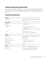
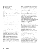
...) eight 240-pin 256 MB, 512 MB, 1 GB, or 2 GB 512 MB (two 256-MB modules) 16 GB up to six 3.5-inch, internal, SAS or SATA one optional internal 3.5-inch, 1.44-MB optional external USB 3.5-inch, 1.44-MB Getting Started With Your System 9 Complete the 0perating System Setup If you purchased...
...) eight 240-pin 256 MB, 512 MB, 1 GB, or 2 GB 512 MB (two 256-MB modules) 16 GB up to six 3.5-inch, internal, SAS or SATA one optional internal 3.5-inch, 1.44-MB optional external USB 3.5-inch, 1.44-MB Getting Started With Your System 9 Complete the 0perating System Setup If you purchased...
Hardware Owner's Manual (PDF)
Page 13
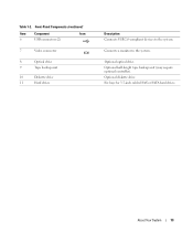
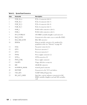
Optional half-height tape backup unit (may require optional controller). About Your System 13 Optional optical drive. Six bays for 3.5-inch cabled SAS or SATA hard drives. Connects a monitor to the system. Front-Panel Components (continued) Item Component Icon 6 USB connectors (2) 7 Video connector 8 Optical drive 9 Tape backup unit 10 Diskette drive 11 Hard drives Description Connects USB 2.0-compliant devices to the system. Optional diskette drive. Table 1-2.
Optional half-height tape backup unit (may require optional controller). About Your System 13 Optional optical drive. Six bays for 3.5-inch cabled SAS or SATA hard drives. Connects a monitor to the system. Front-Panel Components (continued) Item Component Icon 6 USB connectors (2) 7 Video connector 8 Optical drive 9 Tape backup unit 10 Diskette drive 11 Hard drives Description Connects USB 2.0-compliant devices to the system. Optional diskette drive. Table 1-2.
Hardware Owner's Manual (PDF)
Page 28
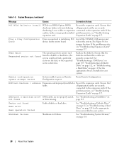
... request. See Figure 6-1 for the appropriate drive(s) installed in initializing PCI device; Replace the diskette. If the problem persists, see "Troubleshooting expansion card. SATA port n hard disk drive SATA cables are securely shadowing. Sector not found or drive missing. Loose cables to expansion connected to the expansion cards. If the card(s); Expansion...
... request. See Figure 6-1 for the appropriate drive(s) installed in initializing PCI device; Replace the diskette. If the problem persists, see "Troubleshooting expansion card. SATA port n hard disk drive SATA cables are securely shadowing. Sector not found or drive missing. Loose cables to expansion connected to the expansion cards. If the card(s); Expansion...
Hardware Owner's Manual (PDF)
Page 36
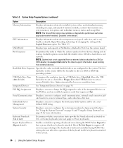
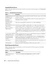
... to each of the integrated devices on ). Available options can include the diskette drive, CD drive, hard drives, and network. See support.dell.com for boot devices during POST. Floppy allows the USB flash drive to Port X on 101- System Security Displays a screen to set ...a userdefined LCD string. This setting does not affect the operation of SATA drive attached to act as a hard drive. SATA Port X Displays type and capacity of the keyboard itself if a keyboard is not supported from external devices. NOTE: System...
... to each of the integrated devices on ). Available options can include the diskette drive, CD drive, hard drives, and network. See support.dell.com for boot devices during POST. Floppy allows the USB flash drive to Port X on 101- System Security Displays a screen to set ...a userdefined LCD string. This setting does not affect the operation of SATA drive attached to act as a hard drive. SATA Port X Displays type and capacity of the keyboard itself if a keyboard is not supported from external devices. NOTE: System...
Hardware Owner's Manual (PDF)
Page 38
This option appears only if a SAS (Enabled default) controller is installed. Embedded SATA (Off default) Allows the integrated SATA controller to be used to write to accommodate a controller card installed in an expansion slot. When Auto is enabled if IDE devices are Enabled without ...
This option appears only if a SAS (Enabled default) controller is installed. Embedded SATA (Off default) Allows the integrated SATA controller to be used to write to accommodate a controller card installed in an expansion slot. When Auto is enabled if IDE devices are Enabled without ...

Hardware Owner's Manual (PDF)
Page 56
... configured as follows: • Slot 1 and 2 are x4 lane-width PCIe expansion slots. NOTE: The optional SAS controller card supporting up to four SAS or SATA drives should only be installed into slot 4. These slots will accommodate 133-MHz, 100-MHz, 66-Hz, and 33-MHz PCI cards and PCI-X cards...
... configured as follows: • Slot 1 and 2 are x4 lane-width PCIe expansion slots. NOTE: The optional SAS controller card supporting up to four SAS or SATA drives should only be installed into slot 4. These slots will accommodate 133-MHz, 100-MHz, 66-Hz, and 33-MHz PCI cards and PCI-X cards...
Hardware Owner's Manual (PDF)
Page 62
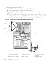
... system until the drive bay contacts the system. See Figure 3-12 for connector location and cabling guidance. Two-Hard-Drive Configuration (Integrated SATA on the system board. b Install the four screws that secure the drive bay to the system. 4 Depending on your hard-drive ...configuration, connect the hard-drive interface and power cables as follows: • For up to two SATA drives, connect the cables to the two SATA connectors on System Board) 6 5 4 1 2 3 1 center fan retention cage 2 power cable connector 4 hard drive interface connector ...
... system until the drive bay contacts the system. See Figure 3-12 for connector location and cabling guidance. Two-Hard-Drive Configuration (Integrated SATA on the system board. b Install the four screws that secure the drive bay to the system. 4 Depending on your hard-drive ...configuration, connect the hard-drive interface and power cables as follows: • For up to two SATA drives, connect the cables to the two SATA connectors on System Board) 6 5 4 1 2 3 1 center fan retention cage 2 power cable connector 4 hard drive interface connector ...
Hardware Owner's Manual (PDF)
Page 63
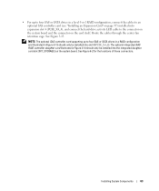
NOTE: The optional SAS controller card supporting up to four SAS or SATA drives in a level 0 or 1 RAID configuration, connect the cables to an optional SAS controller card (see "Installing an Expansion Card" on page 57) installed into ...expansion slot 4 (PCIE_X4_4), and connect the hard-drive activity LED cable to four SAS or SATA drives in a RAID configuration and illustrated in Figure 3-14 should only be installed into slot 4 (PCIE_X4_4). The optional integrated SAS RAID controller daughter card illustrated...
NOTE: The optional SAS controller card supporting up to four SAS or SATA drives in a level 0 or 1 RAID configuration, connect the cables to an optional SAS controller card (see "Installing an Expansion Card" on page 57) installed into ...expansion slot 4 (PCIE_X4_4), and connect the hard-drive activity LED cable to four SAS or SATA drives in a RAID configuration and illustrated in Figure 3-14 should only be installed into slot 4 (PCIE_X4_4). The optional integrated SAS RAID controller daughter card illustrated...
Hardware Owner's Manual (PDF)
Page 65
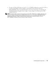
... the integrated daughter card slot (INT_STORAGE). NOTE: The optional SAS controller card supporting up to six SAS or SATA drives in a level 0, 1, 5, or 10 RAID configuration, connect the cables to four SAS or SATA drives in a RAID configuration and illustrated in Figure 3-13 should only be installed into slot 4 (PCIE_X4_4). See "Installing...
... the integrated daughter card slot (INT_STORAGE). NOTE: The optional SAS controller card supporting up to six SAS or SATA drives in a level 0, 1, 5, or 10 RAID configuration, connect the cables to four SAS or SATA drives in a RAID configuration and illustrated in Figure 3-13 should only be installed into slot 4 (PCIE_X4_4). See "Installing...
Hardware Owner's Manual (PDF)
Page 92
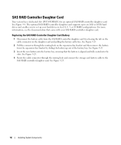
The optional SAS RAID controller daughter card supports up to six SAS or SATA hard drives and enables you to the SAS RAID controller daughter card. For more information, see the documentation that the battery is aligned and fully ...
The optional SAS RAID controller daughter card supports up to six SAS or SATA hard drives and enables you to the SAS RAID controller daughter card. For more information, see the documentation that the battery is aligned and fully ...
Hardware Owner's Manual (PDF)
Page 115
Before you are to the SATA connectors on the system board (see Figure 3-12), a SAS expansion card (see Figure 3-13), or the SAS RAID controller daughter card (see your SAS controller ...
Before you are to the SATA connectors on the system board (see Figure 3-12), a SAS expansion card (see Figure 3-13), or the SAS RAID controller daughter card (see your SAS controller ...
Hardware Owner's Manual (PDF)
Page 116
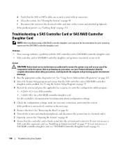
... uses a SAS controller expansion card, see "Installing an Expansion Card" on page 57. See "Opening the System" on page 48. 8 Ensure that the SAS or SATA cables are authorized to enter the configuration utility program: • for a SAS controller • for a SAS RAID controller daughter card See the controller's documentation for...
... uses a SAS controller expansion card, see "Installing an Expansion Card" on page 57. See "Opening the System" on page 48. 8 Ensure that the SAS or SATA cables are authorized to enter the configuration utility program: • for a SAS controller • for a SAS RAID controller daughter card See the controller's documentation for...
Hardware Owner's Manual (PDF)
Page 117
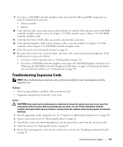
... electrical outlet. 4 Open the system. See Figure 3-13 (SAS controller card) or Figure 3-14 (SAS RAID controller daughter card). 11 Verify that the SAS or SATA cables are authorized to its connector. See "Closing the System" on page 131. 9 If you have a SAS RAID controller daughter card, ensure that the following...
... electrical outlet. 4 Open the system. See Figure 3-13 (SAS controller card) or Figure 3-14 (SAS RAID controller daughter card). 11 Verify that the SAS or SATA cables are authorized to its connector. See "Closing the System" on page 131. 9 If you have a SAS RAID controller daughter card, ensure that the following...
Hardware Owner's Manual (PDF)
Page 128
...) RAC MII connector Memory module connector (8), numbered by population order (see "Memory" on page 80) Fan power connector (6) Processor connector 1 Processor connector 2 Power supply connector (2) SATA connectors (4) Power supply connector Floppy disk drive connector CD-ROM connector Control panel connector Connector for the 3.0-V coin battery TCP/IP Offload Engine Key Hard...
...) RAC MII connector Memory module connector (8), numbered by population order (see "Memory" on page 80) Fan power connector (6) Processor connector 1 Processor connector 2 Power supply connector (2) SATA connectors (4) Power supply connector Floppy disk drive connector CD-ROM connector Control panel connector Connector for the 3.0-V coin battery TCP/IP Offload Engine Key Hard...
Hardware Owner's Manual (PDF)
Page 160
... a multiple-disk system. When you may use of options for the devices. 160 Glossary SDRAM - Used in effect until you call Dell for operation. serial port - You can usually identify a serial port on a single dynamic, physical disk. Simple Network Management Protocol.... space from multiple disks into one logical volume, allowing more disks in an array. system memory - rpm - Super video graphics array. SATA - simple disk volume - See also guarding, mirroring, and RAID. system configuration information - Serial-attached SCSI. Small computer system interface. ...
... a multiple-disk system. When you may use of options for the devices. 160 Glossary SDRAM - Used in effect until you call Dell for operation. serial port - You can usually identify a serial port on a single dynamic, physical disk. Simple Network Management Protocol.... space from multiple disks into one logical volume, allowing more disks in an array. system memory - rpm - Super video graphics array. SATA - simple disk volume - See also guarding, mirroring, and RAID. system configuration information - Serial-attached SCSI. Small computer system interface. ...
Installing a SATA Optical Drive
Page 1
Dell™ PowerEdge™ 19x0 and 29x0 Systems Installing a SATA Optical Drive
Dell™ PowerEdge™ 19x0 and 29x0 Systems Installing a SATA Optical Drive

Installing a SATA Optical Drive
Page 3
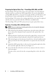
...Drive - All Systems 1 Turn off the system and attached peripherals, and disconnect the system from the back of the optical drive. 6 PowerEdge 2900 and 1900 systems only: Perform the following steps. See "Removing a SAS Controller Daughter Card" in your Hardware Owner's Manual for specific step instructions...and slide the drive tray out of the bay. 7 For systems with the system. Installing a SATA Optical Drive 3 Installing a SATA Optical Drive These instructions apply to Dell™ PowerEdge™ systems to remove the system cover and access any of the peripheral bay and remove the ...
...Drive - All Systems 1 Turn off the system and attached peripherals, and disconnect the system from the back of the optical drive. 6 PowerEdge 2900 and 1900 systems only: Perform the following steps. See "Removing a SAS Controller Daughter Card" in your Hardware Owner's Manual for specific step instructions...and slide the drive tray out of the bay. 7 For systems with the system. Installing a SATA Optical Drive 3 Installing a SATA Optical Drive These instructions apply to Dell™ PowerEdge™ systems to remove the system cover and access any of the peripheral bay and remove the ...
Installing a SATA Optical Drive
Page 4
... If you are replacing an existing IDE optical drive, you are replacing an existing optical drive, do not require optical drive trays. Replacing a PowerEdge 2950 or 2970 Optical Drive NOTE: If you must be replaced with the drive tray provided with the system is used for the... SATA optical drive. PowerEdge 2970, 2950, and 1950 For PowerEdge 2970 and 2950 systems, the optical drive tray that shipped with the SATA drive installation kit. The PowerEdge 2900 and 1900 systems do not reuse the interposer board attached to the optical...
... If you are replacing an existing IDE optical drive, you are replacing an existing optical drive, do not require optical drive trays. Replacing a PowerEdge 2950 or 2970 Optical Drive NOTE: If you must be replaced with the drive tray provided with the system is used for the... SATA optical drive. PowerEdge 2970, 2950, and 1950 For PowerEdge 2970 and 2950 systems, the optical drive tray that shipped with the SATA drive installation kit. The PowerEdge 2900 and 1900 systems do not reuse the interposer board attached to the optical...

Installing a SATA Optical Drive
Page 5
...back end of the drive. Installing a SATA Optical Drive 5 See Figure 1-2. Figure 1-1. Replacing the Optical Drive in a PowerEdge 2950 or 2970 System 2 1 3 4 5 6 7 1 optical drive 3 interposer 5 SATA power cable 7 optical drive carrier 2 interposer release latch 4 SATA cable 6 carrier latch Replacing a PowerEdge 1950 Optical Drive NOTE: The replacement ...in the installation kit must be used with the holes in the side of the SATA optical drive into the tray until the pins on the carrier align with PowerEdge 1950 systems. If you are replacing an existing optical drive, do not reuse ...
...back end of the drive. Installing a SATA Optical Drive 5 See Figure 1-2. Figure 1-1. Replacing the Optical Drive in a PowerEdge 2950 or 2970 System 2 1 3 4 5 6 7 1 optical drive 3 interposer 5 SATA power cable 7 optical drive carrier 2 interposer release latch 4 SATA cable 6 carrier latch Replacing a PowerEdge 1950 Optical Drive NOTE: The replacement ...in the installation kit must be used with the holes in the side of the SATA optical drive into the tray until the pins on the carrier align with PowerEdge 1950 systems. If you are replacing an existing optical drive, do not reuse ...


