
Getting Started Guide
Page 10
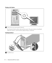
Press the power button on the system and monitor (optional). Installing the Bezel Install the bezel. 8 Getting Started With Your System Adjust the monitor's controls until the displayed image is satisfactory. The power indicators should light. Turning on the System Turn on the system and the monitor.
Press the power button on the system and monitor (optional). Installing the Bezel Install the bezel. 8 Getting Started With Your System Adjust the monitor's controls until the displayed image is satisfactory. The power indicators should light. Turning on the System Turn on the system and the monitor.

Hardware Owner's Manual (PDF)
Page 12
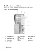
... using certain operating systems. This button can be pressed using the power button and the system is running an ACPI-compliant operating system, the power is on. Front-Panel Components (continued) Item Component Icon 2 Power-on indicator, power button 3 NMI button 4 System identification button 5 LCD panel Description The power-on indicator lights when the system power is turned off . Used to...
... using certain operating systems. This button can be pressed using the power button and the system is running an ACPI-compliant operating system, the power is on. Front-Panel Components (continued) Item Component Icon 2 Power-on indicator, power button 3 NMI button 4 System identification button 5 LCD panel Description The power-on indicator lights when the system power is turned off . Used to...
Hardware Owner's Manual (PDF)
Page 14
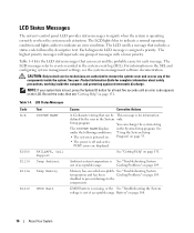
Figure 1-2. Back-Panel Features and Indicators 1 2 3 4 5 6 7 8 1 expansion-card slots (6) 4 system identification button 7 USB connectors (4) 10 serial connector 10 2 remote access connector (optional) 5 system status indicator connector 8 power supply 9 3 system status indicator 6 NIC connector 9 video connector 14 About Your System Back-Panel Features and Indicators Figure 1-2 shows the controls, indicators, and connectors located on the system's back panel.
Figure 1-2. Back-Panel Features and Indicators 1 2 3 4 5 6 7 8 1 expansion-card slots (6) 4 system identification button 7 USB connectors (4) 10 serial connector 10 2 remote access connector (optional) 5 system status indicator connector 8 power supply 9 3 system status indicator 6 NIC connector 9 video connector 14 About Your System Back-Panel Features and Indicators Figure 1-2 shows the controls, indicators, and connectors located on the system's back panel.
Hardware Owner's Manual (PDF)
Page 16
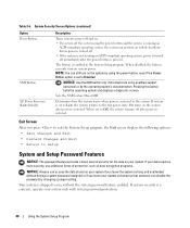
... documentation. You can occur and the probable cause for at least five seconds until an error code appears on page 33. • The power is assigned a priority. The highest priority messages will supersede any of messages with a lower priority. See your system fails to indicate an error... Problems" on page 109. The LCD lights blue to indicate a normal operating condition and lights amber to boot, press the System ID button for each message. The LCD messages refer to remove the system cover and access any group of the components inside the computer, and protecting...
... documentation. You can occur and the probable cause for at least five seconds until an error code appears on page 33. • The power is assigned a priority. The highest priority messages will supersede any of messages with a lower priority. See your system fails to indicate an error... Problems" on page 109. The LCD lights blue to indicate a normal operating condition and lights amber to boot, press the System ID button for each message. The LCD messages refer to remove the system cover and access any group of the components inside the computer, and protecting...
Hardware Owner's Manual (PDF)
Page 40
...access the data stored on your data requires more security, use additional forms of security for the data on the system by using the power button and the system is running and unattended without having a system password assigned or if you without the system password feature enabled. If ...if directed to the system. If system is a concern, operate your system. Exit Screen After you turn off the system using the power button, even if the Power Button option is restored to do so by qualified support personnel or by changing a jumper setting. If system security is set to Off,...
...access the data stored on your data requires more security, use additional forms of security for the data on the system by using the power button and the system is running and unattended without having a system password assigned or if you without the system password feature enabled. If ...if directed to the system. If system is a concern, operate your system. Exit Screen After you turn off the system using the power button, even if the Power Button option is restored to do so by qualified support personnel or by changing a jumper setting. If system security is set to Off,...
Hardware Owner's Manual (PDF)
Page 108
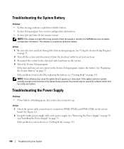
...date and time are not correct in the System Setup program, the problem may lose its system configuration information. Troubleshooting the Power Supply Problem • Power button is turned off the system and disconnect it from the electrical outlet for the time kept in the System Setup program,... replace the battery. See "Removing the Power Supply" on page 50 and "Installing the Power Supply" on the system. 4 Enter the System Setup ...
...date and time are not correct in the System Setup program, the problem may lose its system configuration information. Troubleshooting the Power Supply Problem • Power button is turned off the system and disconnect it from the electrical outlet for the time kept in the System Setup program,... replace the battery. See "Removing the Power Supply" on page 50 and "Installing the Power Supply" on the system. 4 Enter the System Setup ...
Hardware Owner's Manual (PDF)
Page 109
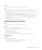
.... Troubleshooting a Fan Problem • System-status indicator is not blinking green and the system does not power up. See "Removing the Power Supply" on page 50 and "Installing the Power Supply" on page 51. Problem • Power button is amber. • Systems management software issues a fan-related error message. • Front panel LCD indicates a problem...
.... Troubleshooting a Fan Problem • System-status indicator is not blinking green and the system does not power up. See "Removing the Power Supply" on page 50 and "Installing the Power Supply" on page 51. Problem • Power button is amber. • Systems management software issues a fan-related error message. • Front panel LCD indicates a problem...
Hardware Owner's Manual (PDF)
Page 155
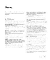
...you can retrieve the data from RAM faster than from the hard drive. bootable diskette - Your system contains an expansion bus that includes power supplies and fans. cache - American National Standards Institute. application - As a precaution, back up files from your operating system. Before ...communications between the processor and RAM. asset tag - An individual code assigned to help you must restart the system by pressing the reset button or by pressing . A copy of a system. A battery that is used in a special section of data or instructions for developing...
...you can retrieve the data from RAM faster than from the hard drive. bootable diskette - Your system contains an expansion bus that includes power supplies and fans. cache - American National Standards Institute. application - As a precaution, back up files from your operating system. Before ...communications between the processor and RAM. asset tag - An individual code assigned to help you must restart the system by pressing the reset button or by pressing . A copy of a system. A battery that is used in a special section of data or instructions for developing...
Hardware Owner's Manual (PDF)
Page 156
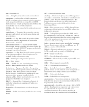
...- DNS - A method of DRAM chips. A system's RAM is usually made up entirely of translating Internet domain names, such as www.dell.com, into an expansion-card connector on your system. EMC - expansion card - control panel - CPU - A program that allows the processor...cm - Centimeter(s). cmos - As they relate to the system by collecting information about the system's components, such as the power button and power indicator. Each component is found in memory modules that relieves the system's processor of data between the processor and memory or between...
...- DNS - A method of DRAM chips. A system's RAM is usually made up entirely of translating Internet domain names, such as www.dell.com, into an expansion-card connector on your system. EMC - expansion card - control panel - CPU - A program that allows the processor...cm - Centimeter(s). cmos - As they relate to the system by collecting information about the system's components, such as the power button and power indicator. Each component is found in memory modules that relieves the system's processor of data between the processor and memory or between...
Hardware Owner's Manual (PDF)
Page 164
... for memory installation, 82 H hard drive troubleshooting, 115 hard drives, 59 installing, 61 removing, 59 hot-plug fans, 53 power supplies, 50 I indicators back-panel, 14 front-panel, 11 LCD, 16 NIC, 15 installing back fan bracket, 80 bezel,...74 expansion cards, 57 expansion-bay bracket, 100 hard drives, 61 memory, 83 memory guidelines, 82 optical drive, 71 power supply, 51 processor, 88 RAC card, 85 RAID battery, 92 system battery, 75 system board, 99 tape backup unit,..., 118 mirroring memory, 83 mouse troubleshooting, 104 N NICs indicators, 15 troubleshooting, 106 NMI button, 12 164 Index
... for memory installation, 82 H hard drive troubleshooting, 115 hard drives, 59 installing, 61 removing, 59 hot-plug fans, 53 power supplies, 50 I indicators back-panel, 14 front-panel, 11 LCD, 16 NIC, 15 installing back fan bracket, 80 bezel,...74 expansion cards, 57 expansion-bay bracket, 100 hard drives, 61 memory, 83 memory guidelines, 82 optical drive, 71 power supply, 51 processor, 88 RAC card, 85 RAID battery, 92 system battery, 75 system board, 99 tape backup unit,..., 118 mirroring memory, 83 mouse troubleshooting, 104 N NICs indicators, 15 troubleshooting, 106 NMI button, 12 164 Index
Hardware Owner's Manual (PDF)
Page 165
...system, 41 PCIe/PCI-X expansion slots, 56 peripheral bay optical drive, 70 tape backup unit, 68 POST accessing system features, 10 power supply installing, 51 removing, 50 troubleshooting, 108 processor replacing, 88 R RAC card installing, 85 RAID controller. See SAS RAID controller ..., 10 status messages LCD, 16 systems management, 23 support contacting Dell, 136 system board connectors, 127 installing, 99 jumpers, 125 removing, 97 system cooling troubleshooting, 109 system features accessing, 10 system identification button, 12 system messages, 23 system password assigning, 41 changing, 42...
...system, 41 PCIe/PCI-X expansion slots, 56 peripheral bay optical drive, 70 tape backup unit, 68 POST accessing system features, 10 power supply installing, 51 removing, 50 troubleshooting, 108 processor replacing, 88 R RAC card installing, 85 RAID controller. See SAS RAID controller ..., 10 status messages LCD, 16 systems management, 23 support contacting Dell, 136 system board connectors, 127 installing, 99 jumpers, 125 removing, 97 system cooling troubleshooting, 109 system features accessing, 10 system identification button, 12 system messages, 23 system password assigning, 41 changing, 42...


