
Getting Started Guide
Page 7
...with your system on installing the stabilizer feet on the CDs that came with your system or from support.dell.com. • CDs included with your Hardware Owner's Manual. Refer to the documentation included with the system to describe changes to troubleshoot the system and install or.... Warranty information may be included within this guide or if the system does not perform as a separate document. • The Hardware Owner's Manual provides information about system features and describes how to the system, software, and/or documentation. Failure to install the feet poses the...
...with your system on installing the stabilizer feet on the CDs that came with your system or from support.dell.com. • CDs included with your Hardware Owner's Manual. Refer to the documentation included with the system to describe changes to troubleshoot the system and install or.... Warranty information may be included within this guide or if the system does not perform as a separate document. • The Hardware Owner's Manual provides information about system features and describes how to the system, software, and/or documentation. Failure to install the feet poses the...
Information Update
Page 4
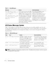
...regulator failure was detected when the processor regulator(s) was enabled. See "Getting Help" in the channel, or possibly the the Hardware Owner's Manual. System Messages Message Causes Corrective Actions The FBD link to the following memory branch has been disabled: Branch x An error ...Update For information on the channel that can occur and the probable cause for information about the by a faulty condition in the Hardware Owner's Manual. Table 1-2. The highest priority messages supersede any group of the DIMMs on the SEL and configuring system management settings, see "...
...regulator failure was detected when the processor regulator(s) was enabled. See "Getting Help" in the channel, or possibly the the Hardware Owner's Manual. System Messages Message Causes Corrective Actions The FBD link to the following memory branch has been disabled: Branch x An error ...Update For information on the channel that can occur and the probable cause for information about the by a faulty condition in the Hardware Owner's Manual. Table 1-2. The highest priority messages supersede any group of the DIMMs on the SEL and configuring system management settings, see "...
Microprocessor Installation Information
Page 1
...Quad-Core Intel® Xeon® Processor 5300 series. See "Installing System Components" in the Hardware Owner's Manual included on the CDs provided with a "II," your system or on support.dell.com. March 2007 See your Product Information Guide for property damage, personal injury, or death. ...NOTICE: Failure to update your system to the latest BIOS and BMC firmware versions prior to be used in the Hardware Owner's Manual included on support.dell.com. 3 Download and flash the latest BIOS version if necessary. 4 Check your system. is intended solely to installing ...
...Quad-Core Intel® Xeon® Processor 5300 series. See "Installing System Components" in the Hardware Owner's Manual included on the CDs provided with a "II," your system or on support.dell.com. March 2007 See your Product Information Guide for property damage, personal injury, or death. ...NOTICE: Failure to update your system to the latest BIOS and BMC firmware versions prior to be used in the Hardware Owner's Manual included on support.dell.com. 3 Download and flash the latest BIOS version if necessary. 4 Check your system. is intended solely to installing ...

Installing a SATA Optical Drive
Page 3
... bay and remove the optical drive from the electrical outlet. 2 Remove the bezel. See "Removing the Bezel" in your Hardware Owner's Manual. 5 Disconnect the data and power cables from the center fan bracket. All Systems 1 Turn off the system and attached peripherals...or in your Hardware Owner's Manual. 4 PowerEdge 1950 systems only: Disconnect and remove the SAS controller daughter card. Installing a SATA Optical Drive These instructions apply to Dell™ PowerEdge™ systems to remove the system cover and access any of the optical drive. 6 PowerEdge 2900 and 1900 systems only:...
... bay and remove the optical drive from the electrical outlet. 2 Remove the bezel. See "Removing the Bezel" in your Hardware Owner's Manual. 5 Disconnect the data and power cables from the center fan bracket. All Systems 1 Turn off the system and attached peripherals...or in your Hardware Owner's Manual. 4 PowerEdge 1950 systems only: Disconnect and remove the SAS controller daughter card. Installing a SATA Optical Drive These instructions apply to Dell™ PowerEdge™ systems to remove the system cover and access any of the optical drive. 6 PowerEdge 2900 and 1900 systems only:...

Installing a SATA Optical Drive
Page 7
Installing a SATA Optical Drive 7 SATA Cable Routing in your Hardware Owner's Manual. 7 Reconnect the system to the power supply connector. Installing the SATA Optical Drive - Figure 1-3. See "SAS Controller Daughter Card" in the PowerEdge 1950 2 1 3 4 6 5 1 SATA data cable 3 chipset ...shroud 5 SATA power cable 2 SATA_A connector on the system and attached peripherals. See "Closing the System" in your Hardware Owner's Manual. 6 Close the system. PowerEdge 2970 or 2950 1 Insert the optical drive tray into the system until it is fully inserted and locked into position....
Installing a SATA Optical Drive 7 SATA Cable Routing in your Hardware Owner's Manual. 7 Reconnect the system to the power supply connector. Installing the SATA Optical Drive - Figure 1-3. See "SAS Controller Daughter Card" in the PowerEdge 1950 2 1 3 4 6 5 1 SATA data cable 3 chipset ...shroud 5 SATA power cable 2 SATA_A connector on the system and attached peripherals. See "Closing the System" in your Hardware Owner's Manual. 6 Close the system. PowerEdge 2970 or 2950 1 Insert the optical drive tray into the system until it is fully inserted and locked into position....

Installing a SATA Optical Drive
Page 8
... your Hardware Owner's Manual. 5 Remove the cable retention bracket from the right interior wall of the chassis by pushing the blue release latch and sliding the bracket toward the front of the system until the bracket detaches from the chassis slots. 6 Route the SATA cable in the cable channel in the PowerEdge 2950...
... your Hardware Owner's Manual. 5 Remove the cable retention bracket from the right interior wall of the chassis by pushing the blue release latch and sliding the bracket toward the front of the system until the bracket detaches from the chassis slots. 6 Route the SATA cable in the cable channel in the PowerEdge 2950...

Installing a SATA Optical Drive
Page 9
.... 4 Use the appropriate power cable provided in your Hardware Owner's Manual. 10 Close the system. For a PowerEdge 2900 system, connect to an available power supply cable. 5 Replace the center fan bracket. Installing a SATA Optical Drive 9 Installing the SATA Optical Drive - See Figure 1-5. - See Figure 1-5. - For a PowerEdge 1900, use the SATA_B connector. - See "Closing the System...
.... 4 Use the appropriate power cable provided in your Hardware Owner's Manual. 10 Close the system. For a PowerEdge 2900 system, connect to an available power supply cable. 5 Replace the center fan bracket. Installing a SATA Optical Drive 9 Installing the SATA Optical Drive - See Figure 1-5. - See Figure 1-5. - For a PowerEdge 1900, use the SATA_B connector. - See "Closing the System...

Installing a SATA Optical Drive
Page 10
SATA Cable Routing in your Hardware Owner's Manual. 10 Reconnect the system to the SAS controller daughter card. 9 Close the system. Figure 1-5. See "Closing the System" in a PowerEdge 2900 or 1900 3 2 4 5 1 1 optical drive 3 SATA data cable 5 SATA power connector on SAS backplane (PowerEdge 2900 only) 2 SATA power cable 4 SATA connector on system board 8 Reconnect the cables to power and turn on the system and attached peripherals. 10 Installing a SATA Optical Drive
SATA Cable Routing in your Hardware Owner's Manual. 10 Reconnect the system to the SAS controller daughter card. 9 Close the system. Figure 1-5. See "Closing the System" in a PowerEdge 2900 or 1900 3 2 4 5 1 1 optical drive 3 SATA data cable 5 SATA power connector on SAS backplane (PowerEdge 2900 only) 2 SATA power cable 4 SATA connector on system board 8 Reconnect the cables to power and turn on the system and attached peripherals. 10 Installing a SATA Optical Drive
Trusted Platform Module (TPM) Update
Page 1
... rights reserved. Other trademarks and trade names may be used in this document to refer to change without the written permission of your Hardware Owner's Manual. November 2007 Trusted Platform Module (TPM) Update Systems that are shipping in China are trademarks of Dell Inc. Reproduction in any manner whatsoever without notice. © 2007...
... rights reserved. Other trademarks and trade names may be used in this document to refer to change without the written permission of your Hardware Owner's Manual. November 2007 Trusted Platform Module (TPM) Update Systems that are shipping in China are trademarks of Dell Inc. Reproduction in any manner whatsoever without notice. © 2007...


