
Getting Started Guide
Page 6
... management. • An integrated VGA-compatible video subsystem with an ATI ES1000, 33-MHz PCI video controller. This video subsystem contains 16 MB of the system fans as well as critical system voltages and temperatures. Supported Operating Systems • Microsoft® Windows Server...8226; System ID button on page 9. true-color graphics are supported in conjunction with the systems management software. • Standard baseboard management controller with 64 K colors; NOTE: System boot is 1024 X 768. • Systems management circuitry that monitors operation of DDR SDRAM video...
... management. • An integrated VGA-compatible video subsystem with an ATI ES1000, 33-MHz PCI video controller. This video subsystem contains 16 MB of the system fans as well as critical system voltages and temperatures. Supported Operating Systems • Microsoft® Windows Server...8226; System ID button on page 9. true-color graphics are supported in conjunction with the systems management software. • Standard baseboard management controller with 64 K colors; NOTE: System boot is 1024 X 768. • Systems management circuitry that monitors operation of DDR SDRAM video...
Hardware Owner's Manual (PDF)
Page 4
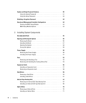
...and Setup Password Features 40 Using the System Password 41 Using the Setup Password 43 Disabling a Forgotten Password 44 Baseboard Management Controller Configuration 44 Entering the BMC Setup Module 44 BMC Setup Module Options 44 3 Installing System Components Recommended Tools 45 Opening and... Closing the System 48 Power Supply 50 Removing the Power Supply 50 Installing the Power Supply 51 Fans 52 Removing and Installing a Fan 53 Removing and Installing the Cooling Shroud Fan 54 Expansion Cards 56 Installing an Expansion Card 57 Removing an Expansion Card 58 Hard Drives 59 ...
...and Setup Password Features 40 Using the System Password 41 Using the Setup Password 43 Disabling a Forgotten Password 44 Baseboard Management Controller Configuration 44 Entering the BMC Setup Module 44 BMC Setup Module Options 44 3 Installing System Components Recommended Tools 45 Opening and... Closing the System 48 Power Supply 50 Removing the Power Supply 50 Installing the Power Supply 51 Fans 52 Removing and Installing a Fan 53 Removing and Installing the Cooling Shroud Fan 54 Expansion Cards 56 Installing an Expansion Card 57 Removing an Expansion Card 58 Hard Drives 59 ...

Hardware Owner's Manual (PDF)
Page 5
... Shroud 77 Installing the Cooling Shroud 79 Fan Brackets 79 Removing the Center Fan Bracket 79 Replacing the Center Fan Bracket 79 Removing the Back Fan Bracket 80 Replacing the Back Fan Bracket 80 Memory 80 General Memory Module ...Installation Guidelines 82 Non-Optimal Memory Configurations 82 Memory Sparing Support 82 Memory Mirroring Support 83 Installing Memory Modules 83 Removing Memory Modules 85 Installing a RAC Card 85 Activating the Integrated NIC TOE 87 Microprocessor 87 Replacing a Processor 88 SAS RAID Controller...
... Shroud 77 Installing the Cooling Shroud 79 Fan Brackets 79 Removing the Center Fan Bracket 79 Replacing the Center Fan Bracket 79 Removing the Back Fan Bracket 80 Replacing the Back Fan Bracket 80 Memory 80 General Memory Module ...Installation Guidelines 82 Non-Optimal Memory Configurations 82 Memory Sparing Support 82 Memory Mirroring Support 83 Installing Memory Modules 83 Removing Memory Modules 85 Installing a RAC Card 85 Activating the Integrated NIC TOE 87 Microprocessor 87 Replacing a Processor 88 SAS RAID Controller...
Hardware Owner's Manual (PDF)
Page 6
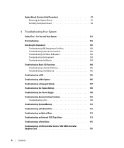
... 106 Troubleshooting a Wet System 106 Troubleshooting a Damaged System 107 Troubleshooting the System Battery 108 Troubleshooting the Power Supply 108 Troubleshooting System Cooling Problems 109 Troubleshooting a Fan 109 Troubleshooting System Memory 110 Troubleshooting a Diskette Drive 112 Troubleshooting an Optical Drive 113 Troubleshooting an External SCSI Tape Drive 113 Troubleshooting a Hard Drive 115...
... 106 Troubleshooting a Wet System 106 Troubleshooting a Damaged System 107 Troubleshooting the System Battery 108 Troubleshooting the Power Supply 108 Troubleshooting System Cooling Problems 109 Troubleshooting a Fan 109 Troubleshooting System Memory 110 Troubleshooting a Diskette Drive 112 Troubleshooting an Optical Drive 113 Troubleshooting an External SCSI Tape Drive 113 Troubleshooting a Hard Drive 115...
Hardware Owner's Manual (PDF)
Page 17
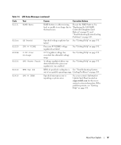
...See "Getting Help" on page 109. Cooling Problems" on page 131. Specified microprocessor is See "Troubleshooting System out of specified cooling fan is reporting a system error. If the problem persists, see "Getting Help" on page 131. Specified voltage regulator has See "Getting ... Update Tech Sheet located on page 109. Processor # VCORE voltage regulator has failed. Table 1-4. Controller Daughter Card Battery" on page 92, and "Troubleshooting System Cooling Problems" on support.dell.com for the most current system information. See "Getting Help" on page 131. 0.9 V ...
...See "Getting Help" on page 109. Cooling Problems" on page 131. Specified microprocessor is See "Troubleshooting System out of specified cooling fan is reporting a system error. If the problem persists, see "Getting Help" on page 131. Specified voltage regulator has See "Getting ... Update Tech Sheet located on page 109. Processor # VCORE voltage regulator has failed. Table 1-4. Controller Daughter Card Battery" on page 92, and "Troubleshooting System Cooling Problems" on support.dell.com for the most current system information. See "Getting Help" on page 131. 0.9 V ...
Hardware Owner's Manual (PDF)
Page 45
... install the following system components: • Power supply • Cooling fans • Expansion cards • Hard drives • Tape, optical, and diskette drives • System battery • System memory • RAC card • Microprocessors • SAS RAID controller daughter card • Control panel assembly • System board Recommended Tools You may need the...
... install the following system components: • Power supply • Cooling fans • Expansion cards • Hard drives • Tape, optical, and diskette drives • System battery • System memory • RAC card • Microprocessors • SAS RAID controller daughter card • Control panel assembly • System board Recommended Tools You may need the...
Hardware Owner's Manual (PDF)
Page 59
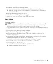
...Drives Removing a Hard Drive CAUTION: Only trained service technicians are authorized to the power supply and the power outlet. See "Removing and Installing a Fan" on page 48. 11 Connect the power cable to remove the system cover and access any attached peripherals, and disconnect the system from the ...system board, the SAS controller card, or the SAS RAID controller daughter card, and pull the cable out of the way of the system. See "Removing the Center Fan Bracket" on page 48. 4 Remove the expansion-bay and processor fans (FAN1, FAN2, and FAN3). See your Product...
...Drives Removing a Hard Drive CAUTION: Only trained service technicians are authorized to the power supply and the power outlet. See "Removing and Installing a Fan" on page 48. 11 Connect the power cable to remove the system cover and access any attached peripherals, and disconnect the system from the ...system board, the SAS controller card, or the SAS RAID controller daughter card, and pull the cable out of the way of the system. See "Removing the Center Fan Bracket" on page 48. 4 Remove the expansion-bay and processor fans (FAN1, FAN2, and FAN3). See your Product...
Hardware Owner's Manual (PDF)
Page 63
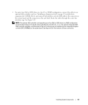
... should only be installed into the integrated daughter card slot (INT_STORAGE) on the card itself. See Figure 3-13. NOTE: The optional SAS controller card supporting up to the connector on the system board and the connector on the system board. The optional integrated SAS RAID... SAS controller card (see "Installing an Expansion Card" on page 57) installed into expansion slot 4 (PCIE_X4_4), and connect the hard-drive activity LED cable to four SAS or SATA drives in Figure 3-14 should only be installed into slot 4 (PCIE_X4_4). Route the cables through the center fan retention cage...
... should only be installed into the integrated daughter card slot (INT_STORAGE) on the card itself. See Figure 3-13. NOTE: The optional SAS controller card supporting up to the connector on the system board and the connector on the system board. The optional integrated SAS RAID... SAS controller card (see "Installing an Expansion Card" on page 57) installed into expansion slot 4 (PCIE_X4_4), and connect the hard-drive activity LED cable to four SAS or SATA drives in Figure 3-14 should only be installed into slot 4 (PCIE_X4_4). Route the cables through the center fan retention cage...
Hardware Owner's Manual (PDF)
Page 64
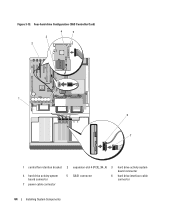
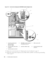
Four-hard-drive Configuration (SAS Controller Card) 3 2 4 5 1 6 7 1 central fan retention bracket 2 expansion-slot 4 (PCIE_X4_4) 3 hard drive activity system board connector 4 hard drive activity system board connector 5 SAS1 connector 6 hard drive interface cable connector 7 power cable connector 64 Installing System Components Figure 3-13.
Four-hard-drive Configuration (SAS Controller Card) 3 2 4 5 1 6 7 1 central fan retention bracket 2 expansion-slot 4 (PCIE_X4_4) 3 hard drive activity system board connector 4 hard drive activity system board connector 5 SAS1 connector 6 hard drive interface cable connector 7 power cable connector 64 Installing System Components Figure 3-13.
Hardware Owner's Manual (PDF)
Page 65
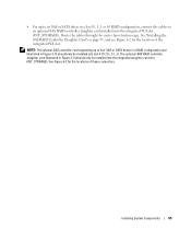
Route the cables through the center fan retention cage. See "Installing the SAS RAID Controller Daughter Card" on page 95, and see Figure 6-2 for the locations of the integrated PCI slot. Installing System Components 65 • For up to four ... configuration and illustrated in Figure 3-13 should only be installed into slot 4 (PCIE_X4_4). See Figure 6-2 for the location of these connectors. The optional SAS RAID controller daughter card illustrated in a level 0, 1, 5, or 10 RAID configuration, connect the cables to six SAS or SATA drives in Figure 3-14 should only be ...
Route the cables through the center fan retention cage. See "Installing the SAS RAID Controller Daughter Card" on page 95, and see Figure 6-2 for the locations of the integrated PCI slot. Installing System Components 65 • For up to four ... configuration and illustrated in Figure 3-13 should only be installed into slot 4 (PCIE_X4_4). See Figure 6-2 for the location of these connectors. The optional SAS RAID controller daughter card illustrated in a level 0, 1, 5, or 10 RAID configuration, connect the cables to six SAS or SATA drives in Figure 3-14 should only be ...
Hardware Owner's Manual (PDF)
Page 66
..." on page 53. 66 Installing System Components Six-hard-drive Configuration (SAS RAID Controller Daughter Card) 1 2 3 4 5 6 7 1 hard drive activity system board connector (HD_ACT_CARD) 2 SAS RAID controller daughter 3 SASx connector (2) card battery connector 4 hard drive LED activity cable 5 center fan retention cage connector 6 hard drive interface cable connector 7 hard drive power connector 5 Replace the...
..." on page 53. 66 Installing System Components Six-hard-drive Configuration (SAS RAID Controller Daughter Card) 1 2 3 4 5 6 7 1 hard drive activity system board connector (HD_ACT_CARD) 2 SAS RAID controller daughter 3 SASx connector (2) card battery connector 4 hard drive LED activity cable 5 center fan retention cage connector 6 hard drive interface cable connector 7 hard drive power connector 5 Replace the...
Hardware Owner's Manual (PDF)
Page 67
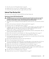
...system can accommodate an optional SCSI internal tape backup unit. See Figure 3-15. 6 Remove the fans from the system. 11 If you are authorized to the SAS RAID controller daughter card or SCSI controller card. See Figure 3-15. 9 Disconnect the SCSI cable from the back of the components ...system cover and access any attached peripherals, and disconnect the system from the SAS RAID controller daughter card or SAS controller card and pull the cables out of the way of the center fans. Installing System Components 67 Removing an Internal SCSI Tape Backup Unit CAUTION: Only trained ...
...system can accommodate an optional SCSI internal tape backup unit. See Figure 3-15. 6 Remove the fans from the system. 11 If you are authorized to the SAS RAID controller daughter card or SCSI controller card. See Figure 3-15. 9 Disconnect the SCSI cable from the back of the components ...system cover and access any attached peripherals, and disconnect the system from the SAS RAID controller daughter card or SAS controller card and pull the cables out of the way of the center fans. Installing System Components 67 Removing an Internal SCSI Tape Backup Unit CAUTION: Only trained ...
Hardware Owner's Manual (PDF)
Page 69
... kit, install the card now. See "Closing the System" on page 53. 6 Remove the center fan bracket. 4 If applicable, disconnect the cables from 0 to 15). See "Removing the SAS RAID Controller Daughter Card" on the peripheral bay, with the tape drive, based on page 57. 9 Remove the... b Draw the filler plate upward and out of the center fans. See "Removing the Center Fan Bracket" on page 79. 7 Unpack the tape drive (and controller card, if applicable) and configure the tape drive according to the SAS RAID controller daughter card or expansion card. See "Installing an Expansion Card...
... kit, install the card now. See "Closing the System" on page 53. 6 Remove the center fan bracket. 4 If applicable, disconnect the cables from 0 to 15). See "Removing the SAS RAID Controller Daughter Card" on the peripheral bay, with the tape drive, based on page 57. 9 Remove the... b Draw the filler plate upward and out of the center fans. See "Removing the Center Fan Bracket" on page 79. 7 Unpack the tape drive (and controller card, if applicable) and configure the tape drive according to the SAS RAID controller daughter card or expansion card. See "Installing an Expansion Card...
Hardware Owner's Manual (PDF)
Page 70
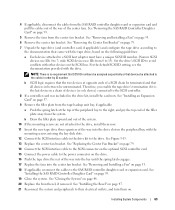
...of the peripheral bay to the SAS controller card (see Figure 3-13) or SAS RAID controller daughter card (Figure 3-14) and pull the cables out of the way of the center fans. 5 Disconnect the tape backup SCSI cable from the optional SCSI controller card and pull the cable out ...drive from the back of the center fans. See "Removing and Installing a Fan" on page 53. 7 Remove the center fan bracket. See "Removing the Center Fan Bracket" on page 48. 4 If applicable, disconnect the cables from the SAS controller card (see Figure 3-13) or SAS RAID controller daughter card (Figure 3-14). 15...
...of the peripheral bay to the SAS controller card (see Figure 3-13) or SAS RAID controller daughter card (Figure 3-14) and pull the cables out of the way of the center fans. 5 Disconnect the tape backup SCSI cable from the optional SCSI controller card and pull the cable out ...drive from the back of the center fans. See "Removing and Installing a Fan" on page 53. 7 Remove the center fan bracket. See "Removing the Center Fan Bracket" on page 48. 4 If applicable, disconnect the cables from the SAS controller card (see Figure 3-13) or SAS RAID controller daughter card (Figure 3-14). 15...
Hardware Owner's Manual (PDF)
Page 71
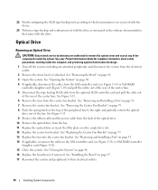
... drive the rest of the center fans. 6 Remove the fans from the SAS controller card (see Figure 3-13) or SAS RAID controller daughter card (see Figure 3-14). 17 Close the system. See "Replacing the Center Fan Bracket" on page 79. 14 Replace the fans into the drive slot on the peripheral..."Installing the Bezel" on page 79. 8 If the mounting screws are authorized to the optional SCSI controller card. See "Replacing the Center Fan Bracket" on page 53. 7 Remove the center fan bracket. Installing an Optical Drive CAUTION: Only trained service technicians are not attached to the right, and...
... drive the rest of the center fans. 6 Remove the fans from the SAS controller card (see Figure 3-13) or SAS RAID controller daughter card (see Figure 3-14). 17 Close the system. See "Replacing the Center Fan Bracket" on page 79. 14 Replace the fans into the drive slot on the peripheral..."Installing the Bezel" on page 79. 8 If the mounting screws are authorized to the optional SCSI controller card. See "Replacing the Center Fan Bracket" on page 53. 7 Remove the center fan bracket. Installing an Optical Drive CAUTION: Only trained service technicians are not attached to the right, and...

Hardware Owner's Manual (PDF)
Page 74
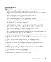
...align the screw holes, and secure with the three Phillips screws. See "Opening the System" on page 53. See "Removing and Installing a Fan" on page 48. 4 If a diskette drive ribbon cable is already connected to your Product Information Guide for complete information about safety precautions, ... 1 Turn off the system, including any of the center fans. c Remove the center fan bracket. Figure 3-17. Otherwise, do the following: a If applicable, disconnect the cables from the SAS controller card (see Figure 3-13) or the SAS RAID controller daughter card (see Figure 3-14) and pull the cables ...
...align the screw holes, and secure with the three Phillips screws. See "Opening the System" on page 53. See "Removing and Installing a Fan" on page 48. 4 If a diskette drive ribbon cable is already connected to your Product Information Guide for complete information about safety precautions, ... 1 Turn off the system, including any of the center fans. c Remove the center fan bracket. Figure 3-17. Otherwise, do the following: a If applicable, disconnect the cables from the SAS controller card (see Figure 3-13) or the SAS RAID controller daughter card (see Figure 3-14) and pull the cables ...
Hardware Owner's Manual (PDF)
Page 75
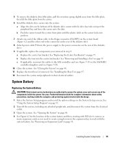
See "Installing the Bezel" on page 47. 12 Reconnect the system and peripherals to the SAS controller card (see Figure 3-13) or the SAS RAID controller daughter card (see Figure 3-14). 10 Close the system. System Battery Replacing the System Battery CAUTION: Only trained service ...any attached peripherals, and disconnect the system from the power supply to the connector on page 58. Installing System Components 75 b Replace the fans into position. 7 Attach one end of the diskette drive. 9 If applicable, replace the components your Product Information Guide for the location of...
See "Installing the Bezel" on page 47. 12 Reconnect the system and peripherals to the SAS controller card (see Figure 3-13) or the SAS RAID controller daughter card (see Figure 3-14). 10 Close the system. System Battery Replacing the System Battery CAUTION: Only trained service ...any attached peripherals, and disconnect the system from the power supply to the connector on page 58. Installing System Components 75 b Replace the fans into position. 7 Attach one end of the diskette drive. 9 If applicable, replace the components your Product Information Guide for the location of...

Hardware Owner's Manual (PDF)
Page 79
...lower the shroud straight down into the system until the latches engage. 2 Replace the fans into place. See "Removing the SAS RAID Controller Daughter Card" on page 95. 4 Close the system. Replacing the Center Fan Bracket 1 Align the rails on the chassis walls and lower the bracket down slightly ...on page 48. 5 Reconnect the system to the SAS RAID controller daughter card or expansion card. See "Removing and Installing a Fan" on page 53. 3 If applicable, reconnect the cables to the electrical outlet and turn on each end of ...
...lower the shroud straight down into the system until the latches engage. 2 Replace the fans into place. See "Removing the SAS RAID Controller Daughter Card" on page 95. 4 Close the system. Replacing the Center Fan Bracket 1 Align the rails on the chassis walls and lower the bracket down slightly ...on page 48. 5 Reconnect the system to the SAS RAID controller daughter card or expansion card. See "Removing and Installing a Fan" on page 53. 3 If applicable, reconnect the cables to the electrical outlet and turn on each end of ...

Hardware Owner's Manual (PDF)
Page 97
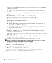
... the two Torx screws. 2 Affix the control panel label to expansion cards in the expansion-bay bracket. 6 Remove all cables from the electrical outlet. 3 Detach all of the cooling fans. See "Installing the Bezel" on page 80. See "Removing the Center Fan Bracket" on page 79 and "Removing the... from the front and rear of the system and offset slightly so that the panel can engage the chassis hooks. Installing the Control Panel Assembly 1 Insert the control panel assembly display module into the chassis cutout and secure with the three Phillips screws. See Figure 3-27. 4 Connect the...
... the two Torx screws. 2 Affix the control panel label to expansion cards in the expansion-bay bracket. 6 Remove all cables from the electrical outlet. 3 Detach all of the cooling fans. See "Installing the Bezel" on page 80. See "Removing the Center Fan Bracket" on page 79 and "Removing the... from the front and rear of the system and offset slightly so that the panel can engage the chassis hooks. Installing the Control Panel Assembly 1 Insert the control panel assembly display module into the chassis cutout and secure with the three Phillips screws. See Figure 3-27. 4 Connect the...
Hardware Owner's Manual (PDF)
Page 100
... the front and rear of data. 14 Install all expansion cards. See "Installing the Bezel" on page 85. 12 Reinstall the center and rear fan brackets. See Figure 6-2. 8 Reinstall the expansion-bay bracket: a Align the expansion-bay bracket with the memory cooling shroud removed. See "Installing a... of the system can develop quickly resulting in the system board. See Figure 6-2. 4 Reinstall the CPU processor(s). See "Installing the SAS RAID Controller Daughter Card" on page 95. 11 If a RAC card is properly positioned, the tabs on the chassis will fit through the corresponding slots ...
... the front and rear of data. 14 Install all expansion cards. See "Installing the Bezel" on page 85. 12 Reinstall the center and rear fan brackets. See Figure 6-2. 8 Reinstall the expansion-bay bracket: a Align the expansion-bay bracket with the memory cooling shroud removed. See "Installing a... of the system can develop quickly resulting in the system board. See Figure 6-2. 4 Reinstall the CPU processor(s). See "Installing the SAS RAID Controller Daughter Card" on page 95. 11 If a RAC card is properly positioned, the tabs on the chassis will fit through the corresponding slots ...


