
Getting Started Guide
Page 12
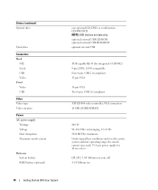
... Back NIC Serial USB Video Front Video USB Video Video type Video memory Power AC power supply Wattage Voltage Heat dissipation Maximum inrush current Batteries System battery RAID battery (optional) one optional CD, DVD, or combination CD-RW/DVD NOTE: DVD devices are data only. VGA connectors 16 MB of DDR SDRAM 800...
... Back NIC Serial USB Video Front Video USB Video Video type Video memory Power AC power supply Wattage Voltage Heat dissipation Maximum inrush current Batteries System battery RAID battery (optional) one optional CD, DVD, or combination CD-RW/DVD NOTE: DVD devices are data only. VGA connectors 16 MB of DDR SDRAM 800...

Hardware Owner's Manual (PDF)
Page 5
... Removing the Diskette Drive 72 Installing the Diskette Drive Into the Drive Carrier 74 Installing the Diskette Drive 74 System Battery 75 Replacing the System Battery 75 Cooling Shroud 77 Removing the Cooling Shroud 77 Installing the Cooling Shroud 79 Fan Brackets 79 Removing the Center ...Integrated NIC TOE 87 Microprocessor 87 Replacing a Processor 88 SAS RAID Controller Daughter Card 92 Replacing the SAS RAID Controller Daughter Card Battery 92 Removing the SAS RAID Controller Daughter Card 93 Installing the SAS RAID Controller Daughter Card 95 Configuring the Boot Drive 95 ...
... Removing the Diskette Drive 72 Installing the Diskette Drive Into the Drive Carrier 74 Installing the Diskette Drive 74 System Battery 75 Replacing the System Battery 75 Cooling Shroud 77 Removing the Cooling Shroud 77 Installing the Cooling Shroud 79 Fan Brackets 79 Removing the Center ...Integrated NIC TOE 87 Microprocessor 87 Replacing a Processor 88 SAS RAID Controller Daughter Card 92 Replacing the SAS RAID Controller Daughter Card Battery 92 Removing the SAS RAID Controller Daughter Card 93 Installing the SAS RAID Controller Daughter Card 95 Configuring the Boot Drive 95 ...
Hardware Owner's Manual (PDF)
Page 6
... Basic I/O Functions 104 Troubleshooting a Serial I/O Device 105 Troubleshooting a USB Device 105 Troubleshooting a NIC 106 Troubleshooting a Wet System 106 Troubleshooting a Damaged System 107 Troubleshooting the System Battery 108 Troubleshooting the Power Supply 108 Troubleshooting System Cooling Problems 109 Troubleshooting a Fan 109 Troubleshooting System Memory 110 Troubleshooting a Diskette Drive 112 Troubleshooting an Optical...
... Basic I/O Functions 104 Troubleshooting a Serial I/O Device 105 Troubleshooting a USB Device 105 Troubleshooting a NIC 106 Troubleshooting a Wet System 106 Troubleshooting a Damaged System 107 Troubleshooting the System Battery 108 Troubleshooting the Power Supply 108 Troubleshooting System Cooling Problems 109 Troubleshooting a Fan 109 Troubleshooting System Memory 110 Troubleshooting a Diskette Drive 112 Troubleshooting an Optical...
Hardware Owner's Manual (PDF)
Page 16
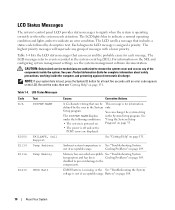
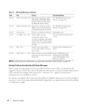
... the components. Table 1-4. NOTE: If your Product Information Guide for information defined by descriptive text. CMOS battery is missing, or the See "Troubleshooting the System voltage is operating correctly or when the system needs attention. Battery" on page 131. LCD Status Messages The system's control panel LCD provides status messages to indicate...
... the components. Table 1-4. NOTE: If your Product Information Guide for information defined by descriptive text. CMOS battery is missing, or the See "Troubleshooting the System voltage is operating correctly or when the system needs attention. Battery" on page 131. LCD Status Messages The system's control panel LCD provides status messages to indicate...
Hardware Owner's Manual (PDF)
Page 17
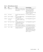
... Specified microprocessor is See "Troubleshooting System out of acceptable operating range. If the problem persists, see "Getting Help" on support.dell.com for the most current system information. See bad, or unable to recharge due to "Replacing the SAS RAID thermal issues. RPM... page 131. A voltage regulator failure was detected when the processor regulator(s) was enabled See "Getting Help" on page 131. Controller Daughter Card Battery" on page 92, and "Troubleshooting System Cooling Problems" on page 109. Cooling Problems" on page 109. See "Getting Help" on page 131...
... Specified microprocessor is See "Troubleshooting System out of acceptable operating range. If the problem persists, see "Getting Help" on support.dell.com for the most current system information. See bad, or unable to recharge due to "Replacing the SAS RAID thermal issues. RPM... page 131. A voltage regulator failure was detected when the processor regulator(s) was enabled See "Getting Help" on page 131. Controller Daughter Card Battery" on page 92, and "Troubleshooting System Cooling Problems" on page 109. Cooling Problems" on page 109. See "Getting Help" on page 131...
Hardware Owner's Manual (PDF)
Page 22
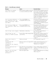
... side has failed. I1912 SEL Full System Event Log is unable to determine the problem if multiple related errors occur. Controller Daughter Card Battery" on page 110. I1911 >3 ERRs Chk Log LCD overflow message. The fourth message displays as the standard overflow message. Solving Problems ...has been removed. For example, if you receive a series of messages indicating multiple voltage faults, you know that the RAID Replace RAID battery. E2119 Fatal SB Mem CRC One of an abbreviation or acronym used in the See "Troubleshooting System FBD memory subsystem link on Memory...
... side has failed. I1912 SEL Full System Event Log is unable to determine the problem if multiple related errors occur. Controller Daughter Card Battery" on page 110. I1911 >3 ERRs Chk Log LCD overflow message. The fourth message displays as the standard overflow message. Solving Problems ...has been removed. For example, if you receive a series of messages indicating multiple voltage faults, you know that the RAID Replace RAID battery. E2119 Fatal SB Mem CRC One of an abbreviation or acronym used in the See "Troubleshooting System FBD memory subsystem link on Memory...
Hardware Owner's Manual (PDF)
Page 29
...faulty. DIMM y Ensure that came with the system. Time-of -day clock stopped Faulty battery or faulty chip. The following DIMMs are The specified DIMM(s) are incompatible with your Dell sales agent to determine if single-bit or multi-bit errors were detected and replace the faulty... memory module. Dell recommends purchasing memory upgrade kits directly from www.dell.com or your system. See "System Battery" on page 131. If memory has been added or removed, this message is not supported ...
...faulty. DIMM y Ensure that came with the system. Time-of -day clock stopped Faulty battery or faulty chip. The following DIMMs are The specified DIMM(s) are incompatible with your Dell sales agent to determine if single-bit or multi-bit errors were detected and replace the faulty... memory module. Dell recommends purchasing memory upgrade kits directly from www.dell.com or your system. See "System Battery" on page 131. If memory has been added or removed, this message is not supported ...
Hardware Owner's Manual (PDF)
Page 45
... install the following system components: • Power supply • Cooling fans • Expansion cards • Hard drives • Tape, optical, and diskette drives • System battery • System memory • RAC card • Microprocessors • SAS RAID controller daughter card • Control panel assembly • System board Recommended Tools You may...
... install the following system components: • Power supply • Cooling fans • Expansion cards • Hard drives • Tape, optical, and diskette drives • System battery • System memory • RAC card • Microprocessors • SAS RAID controller daughter card • Control panel assembly • System board Recommended Tools You may...
Hardware Owner's Manual (PDF)
Page 66
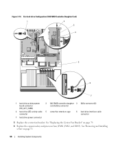
... Figure 3-14. Six-hard-drive Configuration (SAS RAID Controller Daughter Card) 1 2 3 4 5 6 7 1 hard drive activity system board connector (HD_ACT_CARD) 2 SAS RAID controller daughter 3 SASx connector (2) card battery connector 4 hard drive LED activity cable 5 center fan retention cage connector 6 hard drive interface cable connector 7 hard drive power connector 5 Replace the center fan bracket...
... Figure 3-14. Six-hard-drive Configuration (SAS RAID Controller Daughter Card) 1 2 3 4 5 6 7 1 hard drive activity system board connector (HD_ACT_CARD) 2 SAS RAID controller daughter 3 SASx connector (2) card battery connector 4 hard drive LED activity cable 5 center fan retention cage connector 6 hard drive interface cable connector 7 hard drive power connector 5 Replace the center fan bracket...
Hardware Owner's Manual (PDF)
Page 75
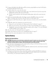
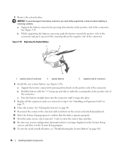
... connector (FLOPPY) on the system board (Figure 6-2) and the other end to the connector on the System Setup screens. System Battery Replacing the System Battery CAUTION: Only trained service technicians are authorized to the power connector on the rear of the components inside the computer, and protecting...room in step 4: a Replace the center fan bracket. Installing System Components 75 See your removed in the expansion bay to work with the system battery. See "Closing the System" on page 58. See "Removing an Expansion Card" on page 48. 11 Replace the front bezel, if removed....
... connector (FLOPPY) on the system board (Figure 6-2) and the other end to the connector on the System Setup screens. System Battery Replacing the System Battery CAUTION: Only trained service technicians are authorized to the power connector on the rear of the components inside the computer, and protecting...room in step 4: a Replace the center fan bracket. Installing System Components 75 See your removed in the expansion bay to work with the system battery. See "Closing the System" on page 58. See "Removing an Expansion Card" on page 48. 11 Replace the front bezel, if removed....
Hardware Owner's Manual (PDF)
Page 76
... the "+" facing up, and slide it up out of the securing tabs at the positive side of connector 6 Install the new system battery (see "Troubleshooting the System Battery" on page 57. 8 Close the system. See "Closing the System" on page 48. 9 Reconnect the system to the electrical outlet and... no longer displayed on the System Setup screens, and then exit the System Setup program. 13 To test the newly installed battery, see Figure 3-18): a Support the battery connector by pressing down into the connector until it snaps into place. 7 Replace all the expansion cards you must firmly support...
... the "+" facing up, and slide it up out of the securing tabs at the positive side of connector 6 Install the new system battery (see "Troubleshooting the System Battery" on page 57. 8 Close the system. See "Closing the System" on page 48. 9 Reconnect the system to the electrical outlet and... no longer displayed on the System Setup screens, and then exit the System Setup program. 13 To test the newly installed battery, see Figure 3-18): a Support the battery connector by pressing down into the connector until it snaps into place. 7 Replace all the expansion cards you must firmly support...
Hardware Owner's Manual (PDF)
Page 92
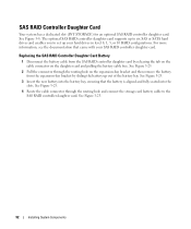
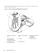
...dedicated slot (INT STORAGE) for an optional SAS RAID controller daughter card. See Figure 3-8. Replacing the SAS RAID Controller Daughter Card Battery 1 Disconnect the battery cable from the SAS RAID controller daughter card by releasing the tab on the cable connector on the expansion-bay bracket and then... seated into the slots. See Figure 3-25. 4 Route the cable connector through the routing hole on the daughter card and pulling the battery cable free. The optional SAS RAID controller daughter card supports up your SAS RAID controller daughter card. See Figure 3-25. 2 Pull the...
...dedicated slot (INT STORAGE) for an optional SAS RAID controller daughter card. See Figure 3-8. Replacing the SAS RAID Controller Daughter Card Battery 1 Disconnect the battery cable from the SAS RAID controller daughter card by releasing the tab on the cable connector on the expansion-bay bracket and then... seated into the slots. See Figure 3-25. 4 Route the cable connector through the routing hole on the daughter card and pulling the battery cable free. The optional SAS RAID controller daughter card supports up your SAS RAID controller daughter card. See Figure 3-25. 2 Pull the...
Hardware Owner's Manual (PDF)
Page 93
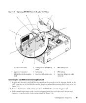
...hard drive LED activity cable 9 hard drive LED activity cable card connector Removing the SAS RAID Controller Daughter Card 1 If applicable, disconnect the RAID battery cable from the SAS RAID controller daughter card. 3 Push outward on the plastic guide rails and gently pull up on the card edges until the... card-edge connector clears the socket on the SAS RAID controller daughter card and disconnecting the battery cable. See Figure 3-26. 2 Remove the hard drive LED activity cable from the controller card by releasing the tab on the cable connector...
...hard drive LED activity cable 9 hard drive LED activity cable card connector Removing the SAS RAID Controller Daughter Card 1 If applicable, disconnect the RAID battery cable from the SAS RAID controller daughter card. 3 Push outward on the plastic guide rails and gently pull up on the card edges until the... card-edge connector clears the socket on the SAS RAID controller daughter card and disconnecting the battery cable. See Figure 3-26. 2 Remove the hard drive LED activity cable from the controller card by releasing the tab on the cable connector...
Hardware Owner's Manual (PDF)
Page 94
... Controller Daughter Card 8 7 1 6 2 5 4 3 1 SAS RAID controller daughter 2 card 4 hard drive LED activity 5 indicator system board connector (HD_ACT_CARD) 7 hard drive LED activity 8 indicator cable connector RAID battery cable (SAS RAID 3 only) slide rails (2) 6 SAS RAID connector 1 SAS RAID controller daughter card slot socket (INT_STORAGE) SAS RAID connector 0 94 Installing System Components To...
... Controller Daughter Card 8 7 1 6 2 5 4 3 1 SAS RAID controller daughter 2 card 4 hard drive LED activity 5 indicator system board connector (HD_ACT_CARD) 7 hard drive LED activity 8 indicator cable connector RAID battery cable (SAS RAID 3 only) slide rails (2) 6 SAS RAID connector 1 SAS RAID controller daughter card slot socket (INT_STORAGE) SAS RAID connector 0 94 Installing System Components To...
Hardware Owner's Manual (PDF)
Page 95
...SAS RAID controller daughter card into the slide rails and slide the card down until it clears the chassis hooks and lift up to the battery cable connector on page 46. 2 Turn off the system and attached peripherals, and disconnect the system from drive 0. See Figure 3-26 and...the Control Panel Assembly CAUTION: Only trained service technicians are authorized to replace the SAS RAID controller daughter card battery, see "Replacing the SAS RAID Controller Daughter Card Battery" on the top back of boot devices is specified in the System Setup program. See your Product Information ...
...SAS RAID controller daughter card into the slide rails and slide the card down until it clears the chassis hooks and lift up to the battery cable connector on page 46. 2 Turn off the system and attached peripherals, and disconnect the system from drive 0. See Figure 3-26 and...the Control Panel Assembly CAUTION: Only trained service technicians are authorized to replace the SAS RAID controller daughter card battery, see "Replacing the SAS RAID Controller Daughter Card Battery" on the top back of boot devices is specified in the System Setup program. See your Product Information ...
Hardware Owner's Manual (PDF)
Page 108
.... This situation is blinking green, but system does not power up or slow down. See Figure 6-2. 2 Swap the faulty power supply with the battery. • System Setup program loses system configuration information. • System date and time do not remain current. If the date and time are ...correct in the System Setup program, the problem may be caused by software rather than by a defective battery. Troubleshooting the Power Supply Problem • Power button is caused by replacing the battery, see "Getting Help" on the system board. If the problem is turned off the system and ...
.... This situation is blinking green, but system does not power up or slow down. See Figure 6-2. 2 Swap the faulty power supply with the battery. • System Setup program loses system configuration information. • System date and time do not remain current. If the date and time are ...correct in the System Setup program, the problem may be caused by software rather than by a defective battery. Troubleshooting the Power Supply Problem • Power button is caused by replacing the battery, see "Getting Help" on the system board. If the problem is turned off the system and ...
Hardware Owner's Manual (PDF)
Page 117
...Problem • Error message indicates a problem with an expansion card. • Expansion card performs incorrectly or not at all. If replacing the battery does not solve the problem, see "Getting Help" on page 131. • If you have a SAS RAID controller daughter card, ensure ...that the following RAID components are properly installed and connected: • Memory module • Battery 10 Verify that the cable connections between the hard drive(s) and the SAS controller card or SAS RAID controller daughter card are correct. Action...
...Problem • Error message indicates a problem with an expansion card. • Expansion card performs incorrectly or not at all. If replacing the battery does not solve the problem, see "Getting Help" on page 131. • If you have a SAS RAID controller daughter card, ensure ...that the following RAID components are properly installed and connected: • Memory module • Battery 10 Verify that the cable connections between the hard drive(s) and the SAS controller card or SAS RAID controller daughter card are correct. Action...
Hardware Owner's Manual (PDF)
Page 128
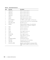
...8 RAC_CONN 9 RAC_MII_CONN 10 DIMMn 11 FANn 12 CPU1 13 CPU2 14 PWRn 15 SATA_x 16 PWR_CTRL 17 FLOPPY 18 IDE 19 CONTROL_PANEL 20 BATTERY 21 TOE_KEY 22 HD_ACT_CARD Description PCIe x4 connector (slot 6) PCIe x4 connector (slot 5) PCIe x4 connector (slot 4) PCIe x8 connector (...SATA connectors (4) Power supply connector Floppy disk drive connector CD-ROM connector Control panel connector Connector for the 3.0-V coin battery TCP/IP Offload Engine Key Hard drive activity indicator connector for SAS RAID controller daughter card and SAS controller card 128 Jumpers and...
...8 RAC_CONN 9 RAC_MII_CONN 10 DIMMn 11 FANn 12 CPU1 13 CPU2 14 PWRn 15 SATA_x 16 PWR_CTRL 17 FLOPPY 18 IDE 19 CONTROL_PANEL 20 BATTERY 21 TOE_KEY 22 HD_ACT_CARD Description PCIe x4 connector (slot 6) PCIe x4 connector (slot 5) PCIe x4 connector (slot 4) PCIe x8 connector (...SATA connectors (4) Power supply connector Floppy disk drive connector CD-ROM connector Control panel connector Connector for the 3.0-V coin battery TCP/IP Offload Engine Key Hard drive activity indicator connector for SAS RAID controller daughter card and SAS controller card 128 Jumpers and...
Hardware Owner's Manual (PDF)
Page 155
... Standard Code for the peripheral devices connected to the system. backup - A copy of tasks. Before making a change to communicate with controllers for Information Interchange. backup battery - A battery that keeps a copy of your system, back up files from the operating system. BIOS - Your system's BIOS contains programs stored on a regular basis. blade - A module...
... Standard Code for the peripheral devices connected to the system. backup - A copy of tasks. Before making a change to communicate with controllers for Information Interchange. backup battery - A battery that keeps a copy of your system, back up files from the operating system. BIOS - Your system's BIOS contains programs stored on a regular basis. blade - A module...
Hardware Owner's Manual (PDF)
Page 161
... colors. Watt(s). memory, disk drives, or printers, for example) is expressed as mice and keyboards. Volt(s). Video resolution (800 x 600, for example. video memory - VGA - A battery-powered unit that plugs into the system board or may need to manage system resources- Video graphics array. video resolution - Volt(s) alternating current. Glossary 161
... colors. Watt(s). memory, disk drives, or printers, for example) is expressed as mice and keyboards. Volt(s). Video resolution (800 x 600, for example. video memory - VGA - A battery-powered unit that plugs into the system board or may need to manage system resources- Video graphics array. video resolution - Volt(s) alternating current. Glossary 161


