Information Update (.pdf)
Page 7
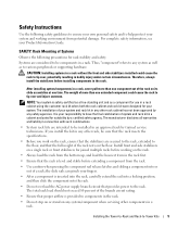
... • Before you work on the rack, ensure that the stabilizers are secured to the rack, extended to the floor, and that provides power to various peripherals or supporting hardware. For complete safety information, see your fingers. • After a component is level and stable before installing ...8226; Use caution when pressing the component rail release latches and sliding a component into the rack. • Do not overload the AC power supply branch circuit that the full weight of your system. If you install the kit in the rack. Safety Instructions Use the following precautions...
... • Before you work on the rack, ensure that the stabilizers are secured to the rack, extended to the floor, and that provides power to various peripherals or supporting hardware. For complete safety information, see your fingers. • After a component is level and stable before installing ...8226; Use caution when pressing the component rail release latches and sliding a component into the rack. • Do not overload the AC power supply branch circuit that the full weight of your system. If you install the kit in the rack. Safety Instructions Use the following precautions...

Installation and Troubleshooting Guide (.htm)
Page 6
Figure 1-10. Figure 1-5. Figure 1-9. Figure 1-6. Figure 1-8. Figure 1-4. Figure 1-7. Figure 1-3. RapidRails Rack Kit Contents 1-8 VersaRails Rack Kit Contents 1-9 One Rack Unit 1-10 Marking the Vertical Rails 1-11 Installing the RapidRails Slide Assemblies . . . . 1-12 Installing the VersaRails Rail Assemblies . . . . . 1-13 Installing the System in the Rack 1-15 Installing the Cable-Management Arm 1-16 Installing the System Status Indicator Cable (If Applicable 1-17 Routing the Power Cords 1-18 1-4 Contents Figures Figure 1-1. Figure 1-2.
Figure 1-10. Figure 1-5. Figure 1-9. Figure 1-6. Figure 1-8. Figure 1-4. Figure 1-7. Figure 1-3. RapidRails Rack Kit Contents 1-8 VersaRails Rack Kit Contents 1-9 One Rack Unit 1-10 Marking the Vertical Rails 1-11 Installing the RapidRails Slide Assemblies . . . . 1-12 Installing the VersaRails Rail Assemblies . . . . . 1-13 Installing the System in the Rack 1-15 Installing the Cable-Management Arm 1-16 Installing the System Status Indicator Cable (If Applicable 1-17 Routing the Power Cords 1-18 1-4 Contents Figures Figure 1-1. Figure 1-2.
Installation and Troubleshooting Guide (.htm)
Page 7
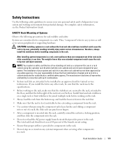
... inserted into the rack, carefully extend the rail into a locking position, and then slide the component into the rack. • Do not overload the AC power supply branch circuit that the rack is level and stable before installing components in the rack. For complete safety information, see the Product Information Guide... the rack. • Always load the rack from the bottom up, and load the heaviest item in the rack first. • Make sure that provides power to the rack.
... inserted into the rack, carefully extend the rail into a locking position, and then slide the component into the rack. • Do not overload the AC power supply branch circuit that the rack is level and stable before installing components in the rack. For complete safety information, see the Product Information Guide... the rack. • Always load the rack from the bottom up, and load the heaviest item in the rack first. • Make sure that provides power to the rack.

Installation and Troubleshooting Guide (.htm)
Page 19
...on the system back panel. For details on cable connections, see your system's Installation and Troubleshooting Guide and your User's Guide. 11 Route the power and I /O cable connectors to their respective connectors on the system back panel. 10 Attach the I /O cables through the cable-management arm,...at this time (see Figure 1-10). Allow some slack in each end of the system to provide strain relief for the power cables. Rack Installation Guide 1-17 Installing the System Status Indicator Cable (If Applicable) system status indicator cable plug system status indicator 8 ...
...on the system back panel. For details on cable connections, see your system's Installation and Troubleshooting Guide and your User's Guide. 11 Route the power and I /O cable connectors to their respective connectors on the system back panel. 10 Attach the I /O cables through the cable-management arm,...at this time (see Figure 1-10). Allow some slack in each end of the system to provide strain relief for the power cables. Rack Installation Guide 1-17 Installing the System Status Indicator Cable (If Applicable) system status indicator cable plug system status indicator 8 ...

Installation and Troubleshooting Guide (.htm)
Page 20
Routing the Power Cords power receptacle housing power cord plug 13 Slide the system in and out of the rack to verify that the cables are routed correctly and do not bind, stretch, ...
Routing the Power Cords power receptacle housing power cord plug 13 Slide the system in and out of the rack to verify that the cables are routed correctly and do not bind, stretch, ...


