
Upgrade the BIOS Before Upgrading Your System (.pdf)
Page 1
... an array larger than that is subject to the RAID hardware. The affected firmware version displays as 4.1-0[Build 7401] in the controller's BIOS, and is strictly forbidden. Printed in trademarks and trade names other than its own. Reproduction in this issue. Trademarks used in any proprietary interest in the U.S.A. Information in the cerc_7401.exe dowloadable package available at support.dell.com. Dell...
... an array larger than that is subject to the RAID hardware. The affected firmware version displays as 4.1-0[Build 7401] in the controller's BIOS, and is strictly forbidden. Printed in trademarks and trade names other than its own. Reproduction in this issue. Trademarks used in any proprietary interest in the U.S.A. Information in the cerc_7401.exe dowloadable package available at support.dell.com. Dell...

Information Update (.pdf)
Page 1
Dell™ PowerEdge™ 1800 Systems Installing the Tower-to-Rack and Rack-to-Tower Kits www.dell.com | support.dell.com
Dell™ PowerEdge™ 1800 Systems Installing the Tower-to-Rack and Rack-to-Tower Kits www.dell.com | support.dell.com
Information Update (.pdf)
Page 3
Dell™ PowerEdge™ 1800 Systems Installing the Tower-to-Rack and Rack-to-Tower Kits www.dell.com | support.dell.com
Dell™ PowerEdge™ 1800 Systems Installing the Tower-to-Rack and Rack-to-Tower Kits www.dell.com | support.dell.com

Information Update (.pdf)
Page 5
... Rack-to -Tower Kit Contents 12 Removing the Slide-Shoulder Screws 12 Removing the Rack Handles 13 Removing the Rack-Adapter Plate 14 Contents 3 Figure 1-9. Figure 1-4. Figure 1-10. Tower-to-Rack Kit Contents 6 Removing the Bezel 7 Removing the System Stabilizer Feet 8 Removing the Right-Side Cover 9 Installing the Rack-Adapter Plate 9 Installing the Rack Handles 10 Installing the Slide-Shoulder Screws 11 Rack-to -Tower Kit Instructions 11 Removing the Slide-Shoulder Screws 12 Removing...
... Rack-to -Tower Kit Contents 12 Removing the Slide-Shoulder Screws 12 Removing the Rack Handles 13 Removing the Rack-Adapter Plate 14 Contents 3 Figure 1-9. Figure 1-4. Figure 1-10. Tower-to-Rack Kit Contents 6 Removing the Bezel 7 Removing the System Stabilizer Feet 8 Removing the Right-Side Cover 9 Installing the Rack-Adapter Plate 9 Installing the Rack Handles 10 Installing the Slide-Shoulder Screws 11 Rack-to -Tower Kit Instructions 11 Removing the Slide-Shoulder Screws 12 Removing...
Information Update (.pdf)
Page 7
... the rack cabinet and rack kit were designed for your system and rack kit in the rack. Systems are intended to be installed in an approved rack by trained service technicians. Therefore, always install the stabilizers before working environment from the rack. • Use caution when pressing the component rail release latches and sliding a component into the rack. • Do not overload the AC power supply...
... the rack cabinet and rack kit were designed for your system and rack kit in the rack. Systems are intended to be installed in an approved rack by trained service technicians. Therefore, always install the stabilizers before working environment from the rack. • Use caution when pressing the component rail release latches and sliding a component into the rack. • Do not overload the AC power supply...
Information Update (.pdf)
Page 8
... from the electrical outlet. 2 Rotate the four bottom-panel system stabilizer feet inward. After you install this kit on your system, see "Rack-to-Tower Kit Instructions." www.dell.com | support.dell.com Tower-to-Rack Kit Instructions NOTE: For instructions on how to install the rack-to-tower kit, see the documentation that came with attached thumbscrews. • One rack-adapter plate. • Six hex-head Phillips screws...
... from the electrical outlet. 2 Rotate the four bottom-panel system stabilizer feet inward. After you install this kit on your system, see "Rack-to-Tower Kit Instructions." www.dell.com | support.dell.com Tower-to-Rack Kit Instructions NOTE: For instructions on how to install the rack-to-tower kit, see the documentation that came with attached thumbscrews. • One rack-adapter plate. • Six hex-head Phillips screws...
Information Update (.pdf)
Page 10
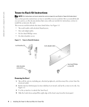
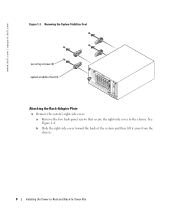
b Slide the right-side cover toward the back of the system and then lift it away from the chassis. 8 Installing the Tower-to-Rack and Rack-to the chassis. www.dell.com | support.dell.com Figure 1-3. Removing the System Stabilizer Feet securing screws (4) system stabilizer feet (4) Attaching the Rack-Adapter Plate 1 Remove the system's right-side cover: a Remove the two back-panel screws that secure the right-side cover to -Tower Kits See Figure 1-4.
b Slide the right-side cover toward the back of the system and then lift it away from the chassis. 8 Installing the Tower-to-Rack and Rack-to the chassis. www.dell.com | support.dell.com Figure 1-3. Removing the System Stabilizer Feet securing screws (4) system stabilizer feet (4) Attaching the Rack-Adapter Plate 1 Remove the system's right-side cover: a Remove the two back-panel screws that secure the right-side cover to -Tower Kits See Figure 1-4.

Information Update (.pdf)
Page 11
c Replace the two back-panel screws to secure the rack-adapter plate to -Tower Kits 9 Installing the Rack-Adapter Plate securing slots (12) rack-adapter plate back-panel screws (2) Installing the Tower-to-Rack and Rack-to the chassis. b Slide the rack-adapter plate toward the front of the system. See Figure 1-5. Figure 1-5. Removing the Right-Side Cover right-side cover back-panel screws (2) 2 Install the rack-adapter plate: a Align the 12 securing tabs on the rack-adapter plate with the 12 securing slots on the chassis. Figure 1-4.
c Replace the two back-panel screws to secure the rack-adapter plate to -Tower Kits 9 Installing the Rack-Adapter Plate securing slots (12) rack-adapter plate back-panel screws (2) Installing the Tower-to-Rack and Rack-to the chassis. b Slide the rack-adapter plate toward the front of the system. See Figure 1-5. Figure 1-5. Removing the Right-Side Cover right-side cover back-panel screws (2) 2 Install the rack-adapter plate: a Align the 12 securing tabs on the rack-adapter plate with the 12 securing slots on the chassis. Figure 1-4.
Information Update (.pdf)
Page 14
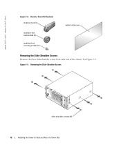
Figure 1-9. www.dell.com | support.dell.com Figure 1-8. Rack-to -Tower Kits Removing the Slide-Shoulder Screws slide-shoulder screws (6) 12 Installing the Tower-to-Rack and Rack-to -Tower Kit Contents stabilizer feet (4) stabilizer-foot swivel disks (4) stabilizer-foot securing screws (4) system side cover Removing the Slide-Shoulder Screws Remove the three slide-shoulder screws from each side of the chassis. See Figure 1-9.
Figure 1-9. www.dell.com | support.dell.com Figure 1-8. Rack-to -Tower Kits Removing the Slide-Shoulder Screws slide-shoulder screws (6) 12 Installing the Tower-to-Rack and Rack-to -Tower Kit Contents stabilizer feet (4) stabilizer-foot swivel disks (4) stabilizer-foot securing screws (4) system side cover Removing the Slide-Shoulder Screws Remove the three slide-shoulder screws from each side of the chassis. See Figure 1-9.

Information Update (.pdf)
Page 15
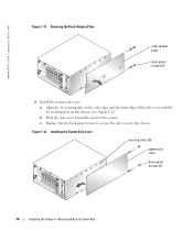
b Slide the rack-adapter plate toward the back of the system and then lift it away from the chassis. Removing the Rack Handles rack handles (2) hex-head Phillips screws (6) Attaching the Side Cover 1 Remove the rack-adapter plate: a Remove the two back-panel screws that secure each rack handle to the chassis. Removing the Rack Handles Remove the three hex-head Phillips screws that secure the rack-adapter plate to the chassis. Installing the Tower-to-Rack and Rack-to-Tower Kits 13 See Figure 1-10. See Figure 1-11. Figure 1-10.
b Slide the rack-adapter plate toward the back of the system and then lift it away from the chassis. Removing the Rack Handles rack handles (2) hex-head Phillips screws (6) Attaching the Side Cover 1 Remove the rack-adapter plate: a Remove the two back-panel screws that secure each rack handle to the chassis. Removing the Rack Handles Remove the three hex-head Phillips screws that secure the rack-adapter plate to the chassis. Installing the Tower-to-Rack and Rack-to-Tower Kits 13 See Figure 1-10. See Figure 1-11. Figure 1-10.
Information Update (.pdf)
Page 16
... the side cover to -Tower Kits www.dell.com | support.dell.com Figure 1-11. Figure 1-12. Removing the Rack-Adapter Plate rack-adapter plate back-panel screws (2) 2 Install the system side cover: a Align the 16 securing tabs on the side edges and the front edge of the system. Installing the System Side Cover securing slots (16) system side cover back-panel screws (2) 14 Installing the Tower-to-Rack and Rack-to the chassis. See...
... the side cover to -Tower Kits www.dell.com | support.dell.com Figure 1-11. Figure 1-12. Removing the Rack-Adapter Plate rack-adapter plate back-panel screws (2) 2 Install the system side cover: a Align the 16 securing tabs on the side edges and the front edge of the system. Installing the System Side Cover securing slots (16) system side cover back-panel screws (2) 14 Installing the Tower-to-Rack and Rack-to the chassis. See...
Information Update (.pdf)
Page 18
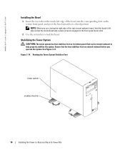
... rack-mount system's bezel, hold the bezel's left edge of the bezel into the corresponding slots on the system front panel, and pivot the bezel inward to its bottom panel that can be rotated outward to help properly stabilize the system. Figure 1-14. NOTE: When you operate the...system stabilizer feet (4) 16 Installing the Tower-to-Rack and Rack-to-Tower Kits See Figure 1-14. www.dell.com | support.dell.com Installing the Bezel 1 Insert the two tabs on the inside bezel tabs remain properly engaged in the front-panel bezel slots. 2 Use the system key to lock the bezel. Stabilizing...
... rack-mount system's bezel, hold the bezel's left edge of the bezel into the corresponding slots on the system front panel, and pivot the bezel inward to its bottom panel that can be rotated outward to help properly stabilize the system. Figure 1-14. NOTE: When you operate the...system stabilizer feet (4) 16 Installing the Tower-to-Rack and Rack-to-Tower Kits See Figure 1-14. www.dell.com | support.dell.com Installing the Bezel 1 Insert the two tabs on the inside bezel tabs remain properly engaged in the front-panel bezel slots. 2 Use the system key to lock the bezel. Stabilizing...
Installing the DRAC 4/P (.pdf)
Page 1
..., download updated drivers from the Dell™ Support website at support.dell.com. Trademarks used in the U.S.A. Microsoft and Windows are run in any Operating System Intel NIC drivers, family driver version 7.1, may be used in this issue, download updated drivers from the Dell Support website at support.dell.com. All rights reserved. Other trademarks and trade names may fail when running the Red Hat Enterprise Linux (version 2.1) or Red Hat Enterprise Linux (version 3) operating system. Dell Inc. Driver Issues When Running the...
..., download updated drivers from the Dell™ Support website at support.dell.com. Trademarks used in the U.S.A. Microsoft and Windows are run in any Operating System Intel NIC drivers, family driver version 7.1, may be used in this issue, download updated drivers from the Dell Support website at support.dell.com. All rights reserved. Other trademarks and trade names may fail when running the Red Hat Enterprise Linux (version 2.1) or Red Hat Enterprise Linux (version 3) operating system. Dell Inc. Driver Issues When Running the...

Installation and Troubleshooting Guide (.htm)
Page 5
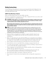
Contents Safety Instructions 1-5 SAFETY: Rack Mounting of Systems 1-5 Installation Instructions 1-6 Before You Begin 1-6 Installation Tasks 1-7 Recommended Tools and Supplies 1-7 RapidRails Rack Kit Contents 1-7 VersaRails Rack Kit Contents 1-8 Removing the Rack Doors 1-9 Marking the Rack 1-10 Installing the RapidRails Slide Assemblies 1-11 Installing the VersaRails Slide Assemblies 1-12 Installing the System in the Rack 1-14 Installing the Cable-Management Arm 1-15 Installing the Cable Tray 1-15 Securing the Cable-Management Arm 1-15 Replacing the Rack Doors 1-19 Index 1-21...
Contents Safety Instructions 1-5 SAFETY: Rack Mounting of Systems 1-5 Installation Instructions 1-6 Before You Begin 1-6 Installation Tasks 1-7 Recommended Tools and Supplies 1-7 RapidRails Rack Kit Contents 1-7 VersaRails Rack Kit Contents 1-8 Removing the Rack Doors 1-9 Marking the Rack 1-10 Installing the RapidRails Slide Assemblies 1-11 Installing the VersaRails Slide Assemblies 1-12 Installing the System in the Rack 1-14 Installing the Cable-Management Arm 1-15 Installing the Cable Tray 1-15 Securing the Cable-Management Arm 1-15 Replacing the Rack Doors 1-19 Index 1-21...
Installation and Troubleshooting Guide (.htm)
Page 7
... to various peripherals or supporting hardware. If you install the kit in any other rack cabinet has not been approved by any system as well as a component for use in a rack cabinet using the customer rack kit when both the rack cabinet and rack kit were designed for suitability by trained service technicians. SAFETY: Rack Mounting of more than one time. The weight of Systems Observe the...
... to various peripherals or supporting hardware. If you install the kit in any other rack cabinet has not been approved by any system as well as a component for use in a rack cabinet using the customer rack kit when both the rack cabinet and rack kit were designed for suitability by trained service technicians. SAFETY: Rack Mounting of more than one time. The weight of Systems Observe the...
Installation and Troubleshooting Guide (.htm)
Page 8
... service technicians installing one or more systems in an open-frame relay rack or in the rack. Use extreme caution while moving the rack cabinet. Installation Instructions This installation guide provides instructions for installing both RapidRails and VersaRails rack kits are similar. NOTICE: The VersaRails rack kit is required for support and to -rack conversion kit. CAUTION: Rack cabinets can be involved. Instructions for your system's Product Information Guide for each system installed in a rack cabinet. Use...
... service technicians installing one or more systems in an open-frame relay rack or in the rack. Use extreme caution while moving the rack cabinet. Installation Instructions This installation guide provides instructions for installing both RapidRails and VersaRails rack kits are similar. NOTICE: The VersaRails rack kit is required for support and to -rack conversion kit. CAUTION: Rack cabinets can be involved. Instructions for your system's Product Information Guide for each system installed in a rack cabinet. Use...
Installation and Troubleshooting Guide (.htm)
Page 9
... cable tray Rack Installation Guide 1-7 CAUTION: After installing systems in marking the mounting holes to be used • A measuring ruler or tape measure RapidRails Rack Kit Contents The RapidRails rack kit includes the following tasks in their numbered order: 1 Removing the rack doors 2 Marking the rack (if necessary) 3 Installing the rail assemblies in the rack: • RapidRails installation • VersaRails installation 4 Installing the system in the rack 5 Installing the cable-management arm 6 Routing cables 7 Replacing the rack doors...
... cable tray Rack Installation Guide 1-7 CAUTION: After installing systems in marking the mounting holes to be used • A measuring ruler or tape measure RapidRails Rack Kit Contents The RapidRails rack kit includes the following tasks in their numbered order: 1 Removing the rack doors 2 Marking the rack (if necessary) 3 Installing the rail assemblies in the rack: • RapidRails installation • VersaRails installation 4 Installing the system in the rack 5 Installing the cable-management arm 6 Routing cables 7 Replacing the rack doors...

Installation and Troubleshooting Guide (.htm)
Page 11
... remove or install them by yourself. Figure 1-2. CAUTION: Store the two doors where they will not injure someone if the doors accidently fall over. Rack Installation Guide 1-9 VersaRails Rack Kit Contents cable tray system status indicator cable (if applicable) cable-management arm cable-management arm retainer VersaRails slide assemblies 10-32 x 0.5-inch flangehead Phillips screws (8) Removing the Rack Doors See the procedures for removing doors in the documentation...
... remove or install them by yourself. Figure 1-2. CAUTION: Store the two doors where they will not injure someone if the doors accidently fall over. Rack Installation Guide 1-9 VersaRails Rack Kit Contents cable tray system status indicator cable (if applicable) cable-management arm cable-management arm retainer VersaRails slide assemblies 10-32 x 0.5-inch flangehead Phillips screws (8) Removing the Rack Doors See the procedures for removing doors in the documentation...

Installation and Troubleshooting Guide (.htm)
Page 13
... and the push button pops out and clicks. The top mounting hook on the rail assembly's front-mounting bracket flange should enter the top hole between the marks on the vertical rails. 2 Push the slide assembly forward until the mounting hooks seat in the appropriate hole, and then push down on the rack (see Figure 1-5). Rack Installation Guide 1-11 Figure...
... and the push button pops out and clicks. The top mounting hook on the rail assembly's front-mounting bracket flange should enter the top hole between the marks on the vertical rails. 2 Push the slide assembly forward until the mounting hooks seat in the appropriate hole, and then push down on the rack (see Figure 1-5). Rack Installation Guide 1-11 Figure...

Installation and Troubleshooting Guide (.htm)
Page 15
... to secure the slide assembly to the back vertical rail. 5 Repeat steps 1 through 4 for the slide assembly on both sides of the rack. Installing the VersaRails Rail Assemblies slide-assembly mounting-bracket flange front of the rack. NOTE: Ensure that the rails are mounted at the same vertical position on the other side of rack slide assemblies (2) Rack Installation Guide 1-13 Figure 1-6.
... to secure the slide assembly to the back vertical rail. 5 Repeat steps 1 through 4 for the slide assembly on both sides of the rack. Installing the VersaRails Rail Assemblies slide-assembly mounting-bracket flange front of the rack. NOTE: Ensure that the rails are mounted at the same vertical position on the other side of rack slide assemblies (2) Rack Installation Guide 1-13 Figure 1-6.


