Information Update (.pdf)
Page 7
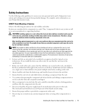
...should not exceed 80 percent of the rack on any safety agencies. Systems are secured to the rack, extended to the floor, and that provides power to components in the rack. • Do not step on or stand on its slide assemblies at one extended component could cause the rack ... the rack. • Use caution when pressing the component rail release latches and sliding a component into the rack. • Do not overload the AC power supply branch circuit that the full weight of Systems Observe the following safety guidelines to ensure your own personal safety and to be components in...
...should not exceed 80 percent of the rack on any safety agencies. Systems are secured to the rack, extended to the floor, and that provides power to components in the rack. • Do not step on or stand on its slide assemblies at one extended component could cause the rack ... the rack. • Use caution when pressing the component rail release latches and sliding a component into the rack. • Do not overload the AC power supply branch circuit that the full weight of Systems Observe the following safety guidelines to ensure your own personal safety and to be components in...

Installation and Troubleshooting Guide (.htm)
Page 6
Figures Figure 1-1. Figure 1-3. Figure 1-8. Figure 1-2. Figure 1-7. RapidRails Rack Kit Contents 1-8 VersaRails Rack Kit Contents 1-9 One Rack Unit 1-10 Marking the Vertical Rails 1-11 Installing the RapidRails Slide Assemblies . . . . 1-12 Installing the VersaRails Rail Assemblies . . . . . 1-13 Installing the System in the Rack 1-15 Installing the Cable-Management Arm 1-16 Installing the System Status Indicator Cable (If Applicable 1-17 Routing the Power Cords 1-18 1-4 Contents Figure 1-6. Figure 1-9. Figure 1-4. Figure 1-10. Figure 1-5.
Figures Figure 1-1. Figure 1-3. Figure 1-8. Figure 1-2. Figure 1-7. RapidRails Rack Kit Contents 1-8 VersaRails Rack Kit Contents 1-9 One Rack Unit 1-10 Marking the Vertical Rails 1-11 Installing the RapidRails Slide Assemblies . . . . 1-12 Installing the VersaRails Rail Assemblies . . . . . 1-13 Installing the System in the Rack 1-15 Installing the Cable-Management Arm 1-16 Installing the System Status Indicator Cable (If Applicable 1-17 Routing the Power Cords 1-18 1-4 Contents Figure 1-6. Figure 1-9. Figure 1-4. Figure 1-10. Figure 1-5.
Installation and Troubleshooting Guide (.htm)
Page 7
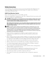
.... • Use caution when pressing the component rail release latches and sliding a component into the rack. • Do not overload the AC power supply branch circuit that provides power to the floor, and that the stabilizers are intended to tip over , potentially resulting in an approved rack by any system as well...
.... • Use caution when pressing the component rail release latches and sliding a component into the rack. • Do not overload the AC power supply branch circuit that provides power to the floor, and that the stabilizers are intended to tip over , potentially resulting in an approved rack by any system as well...

Installation and Troubleshooting Guide (.htm)
Page 19
... respective connectors on the system back panel. Allow some slack in the cable-management arm to prevent damage to provide strain relief for the power cables. Rack Installation Guide 1-17 Figure 1-9. Do not fully tighten the tie-wraps at this time (see Figure 1-10). CAUTION: Allow... the System Status Indicator Cable (If Applicable) system status indicator cable plug system status indicator 8 Connect the power cords to their receptacles on the system back panel. 7 Connect the power cables to their receptacles on the back panel (see Figure 1-10). NOTE: Use the strain-relief loop ...
... respective connectors on the system back panel. Allow some slack in the cable-management arm to prevent damage to provide strain relief for the power cables. Rack Installation Guide 1-17 Figure 1-9. Do not fully tighten the tie-wraps at this time (see Figure 1-10). CAUTION: Allow... the System Status Indicator Cable (If Applicable) system status indicator cable plug system status indicator 8 Connect the power cords to their receptacles on the system back panel. 7 Connect the power cables to their receptacles on the back panel (see Figure 1-10). NOTE: Use the strain-relief loop ...

Installation and Troubleshooting Guide (.htm)
Page 20
... back of the rack to verify that secure the front of the slide, and then slide the system completely into the rack. Routing the Power Cords power receptacle housing power cord plug 13 Slide the system in the extended position. To push the system back into the rack, press the slide release latch...
... back of the rack to verify that secure the front of the slide, and then slide the system completely into the rack. Routing the Power Cords power receptacle housing power cord plug 13 Slide the system in the extended position. To push the system back into the rack, press the slide release latch...


