Information Update (.pdf)
Page 7
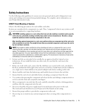
...the rack. • Always load the rack from the bottom up, and load the heaviest item in the rack first. • Ensure that provides power to any system/component when servicing other rack, be installed in a rack. Thus, "component" refers to the rack. Therefore, always install the .... • Use caution when pressing the component rail release latches and sliding a component into the rack. • Do not overload the AC power supply branch circuit that the rack is your responsibility to -Tower Kits 5 For complete safety information, see your system and rack kit in any...
...the rack. • Always load the rack from the bottom up, and load the heaviest item in the rack first. • Ensure that provides power to any system/component when servicing other rack, be installed in a rack. Thus, "component" refers to the rack. Therefore, always install the .... • Use caution when pressing the component rail release latches and sliding a component into the rack. • Do not overload the AC power supply branch circuit that the rack is your responsibility to -Tower Kits 5 For complete safety information, see your system and rack kit in any...

Installation and Troubleshooting Guide (.htm)
Page 6
Figure 1-2. Figure 1-8. Figure 1-5. Figure 1-10. Figure 1-9. Figure 1-3. Figure 1-7. Figures Figure 1-1. Figure 1-4. RapidRails Rack Kit Contents 1-8 VersaRails Rack Kit Contents 1-9 One Rack Unit 1-10 Marking the Vertical Rails 1-11 Installing the RapidRails Slide Assemblies . . . . 1-12 Installing the VersaRails Rail Assemblies . . . . . 1-13 Installing the System in the Rack 1-15 Installing the Cable-Management Arm 1-16 Installing the System Status Indicator Cable (If Applicable 1-17 Routing the Power Cords 1-18 1-4 Contents Figure 1-6.
Figure 1-2. Figure 1-8. Figure 1-5. Figure 1-10. Figure 1-9. Figure 1-3. Figure 1-7. Figures Figure 1-1. Figure 1-4. RapidRails Rack Kit Contents 1-8 VersaRails Rack Kit Contents 1-9 One Rack Unit 1-10 Marking the Vertical Rails 1-11 Installing the RapidRails Slide Assemblies . . . . 1-12 Installing the VersaRails Rail Assemblies . . . . . 1-13 Installing the System in the Rack 1-15 Installing the Cable-Management Arm 1-16 Installing the System Status Indicator Cable (If Applicable 1-17 Routing the Power Cords 1-18 1-4 Contents Figure 1-6.
Installation and Troubleshooting Guide (.htm)
Page 7
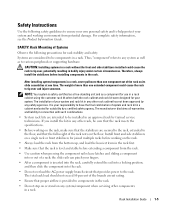
... from the rack. • Use caution when pressing the component rail release latches and sliding a component into the rack. • Do not overload the AC power supply branch circuit that the rack is inserted into the rack, carefully extend the rail into a locking position, and then slide the component into or... the rack. • Always load the rack from the bottom up, and load the heaviest item in the rack first. • Make sure that provides power to be components in the rack.
... from the rack. • Use caution when pressing the component rail release latches and sliding a component into the rack. • Do not overload the AC power supply branch circuit that the rack is inserted into the rack, carefully extend the rail into a locking position, and then slide the component into or... the rack. • Always load the rack from the bottom up, and load the heaviest item in the rack first. • Make sure that provides power to be components in the rack.

Installation and Troubleshooting Guide (.htm)
Page 19
...on the system back panel. For details on cable connections, see your system's Installation and Troubleshooting Guide and your User's Guide. 11 Route the power and I /O cable connectors to their respective connectors on the system back panel. Do not fully tighten the tie-wraps at this time (see... Figure 1-10). Installing the System Status Indicator Cable (If Applicable) system status indicator cable plug system status indicator 8 Connect the power cords to their receptacles on the back of the cable-management arm). Rack Installation Guide 1-17 Figure 1-9. 7 Connect the...
...on the system back panel. For details on cable connections, see your system's Installation and Troubleshooting Guide and your User's Guide. 11 Route the power and I /O cable connectors to their respective connectors on the system back panel. Do not fully tighten the tie-wraps at this time (see... Figure 1-10). Installing the System Status Indicator Cable (If Applicable) system status indicator cable plug system status indicator 8 Connect the power cords to their receptacles on the back of the cable-management arm). Rack Installation Guide 1-17 Figure 1-9. 7 Connect the...

Installation and Troubleshooting Guide (.htm)
Page 20
... do not bind, stretch, or pinch with the straps, and close the wire covers over the cable-management arm. Figure 1-10. Routing the Power Cords power receptacle housing power cord plug 13 Slide the system in the extended position. b Slide the system forward to verify that the cable slack is neither too tight...
... do not bind, stretch, or pinch with the straps, and close the wire covers over the cable-management arm. Figure 1-10. Routing the Power Cords power receptacle housing power cord plug 13 Slide the system in the extended position. b Slide the system forward to verify that the cable slack is neither too tight...


