
Command Line Interface Guide
Page 414
... System Contact: System Name: RS1 System location: System MAC Address: 00:00:b0:00:00:00 Sys Object ID: 1.3.6.1.4.1.674.10895.3020 PowerConnect 5400 Type: Main Power Supply ok Status Redundant Power ok Supply Status: Fan 1 Status: OK Fan 2 Status: OK console> set system The set system {iscsi | dva} • iscsi - Syntax • set system...
... System Contact: System Name: RS1 System location: System MAC Address: 00:00:b0:00:00:00 Sys Object ID: 1.3.6.1.4.1.674.10895.3020 PowerConnect 5400 Type: Main Power Supply ok Status Redundant Power ok Supply Status: Fan 1 Status: OK Fan 2 Status: OK console> set system The set system {iscsi | dva} • iscsi - Syntax • set system...

User's Guide
Page 3
Contents 1 Introduction 13 PowerConnect 54xx Series Systems 13 Features 14 General Features 14 MAC Address Supported Features 15 Layer 2 Features 16 VLAN Supported Features 17 Spanning Tree Protocol ...Additional CLI Documentation 23 2 Hardware Description 25 Device Port Configurations 25 PowerConnect 54xx Series Systems Front Panel Port Description 25 PowerConnect Back Panel Port Description 26 Device Ports 26 Physical Dimensions 27 LED Definitions 27 Port LEDs 27 System LEDs 28 Hardware Components 29 Power Supplies 29 Reset Button 30 Ventilation System 30 Contents 3
Contents 1 Introduction 13 PowerConnect 54xx Series Systems 13 Features 14 General Features 14 MAC Address Supported Features 15 Layer 2 Features 16 VLAN Supported Features 17 Spanning Tree Protocol ...Additional CLI Documentation 23 2 Hardware Description 25 Device Port Configurations 25 PowerConnect 54xx Series Systems Front Panel Port Description 25 PowerConnect Back Panel Port Description 26 Device Ports 26 Physical Dimensions 27 LED Definitions 27 Port LEDs 27 System LEDs 28 Hardware Components 29 Power Supplies 29 Reset Button 30 Ventilation System 30 Contents 3

User's Guide
Page 4
3 Installing the PowerConnect Device 31 Installation Precautions 31 Site Requirements 32 Unpacking 32 Package Contents 32 Unpacking the Device 32 Mounting the Device 33 Overview 33 Mounting the System 33 Installing the Device without a Rack 34 Connecting the Device 34 Connecting a Device to a Terminal 34 Connecting a Device to a Power Supply 36 Port Connections, Cables...
3 Installing the PowerConnect Device 31 Installation Precautions 31 Site Requirements 32 Unpacking 32 Package Contents 32 Unpacking the Device 32 Mounting the Device 33 Overview 33 Mounting the System 33 Installing the Device without a Rack 34 Connecting the Device 34 Connecting a Device to a Terminal 34 Connecting a Device to a Power Supply 36 Port Connections, Cables...

User's Guide
Page 26
... Only one time. The default baud rate is to connect a Redundant Power Supply (RPS) to be configured from 2400 bps up to either 110V or 220V power supplies. Figure 2-2. RS-232 Console Port One DB-9 connector for power, as 1000Base-SX or LX. PowerConnect Back Panel Port Description The device back panel contains connectors for a serial...
... Only one time. The default baud rate is to connect a Redundant Power Supply (RPS) to be configured from 2400 bps up to either 110V or 220V power supplies. Figure 2-2. RS-232 Console Port One DB-9 connector for power, as 1000Base-SX or LX. PowerConnect Back Panel Port Description The device back panel contains connectors for a serial...

User's Guide
Page 27
... are present, and a connector is inserted in the SFP port, the SFP port is active, unless the copper connector of the Base-T port of links, power supplies, fans, and system diagnostics. The port is indicated on the right LED. Physical Dimensions The device has the following table: Table 2-1. Port LEDs 10/100...
... are present, and a connector is inserted in the SFP port, the SFP port is active, unless the copper connector of the Base-T port of links, power supplies, fans, and system diagnostics. The port is indicated on the right LED. Physical Dimensions The device has the following table: Table 2-1. Port LEDs 10/100...

User's Guide
Page 28
... LEDs 28 Hardware Description When the SFP port is connected, the Duplex LED on the left side of the front panel, provide information about the power supplies, fans, thermal conditions, and diagnostics. Figure 2-6 illustrates the system LEDs. Green Flashing The port is currently up. Figure 2-5. SFP Port LED The SFP port LED...
... LEDs 28 Hardware Description When the SFP port is connected, the Duplex LED on the left side of the front panel, provide information about the power supplies, fans, thermal conditions, and diagnostics. Figure 2-6 illustrates the system LEDs. Green Flashing The port is currently up. Figure 2-5. SFP Port LED The SFP port LED...

User's Guide
Page 29
... temperature is not currently operating. For more fans are not operating. Hardware Description 29 To power up the device, only one power supply has an outage, the second power supply automatically continues providing power to an external power supply unit (DC unit). If one power supply is currently running a diagnostic test. Load sharing is called an RPS unit. The external...
... temperature is not currently operating. For more fans are not operating. Hardware Description 29 To power up the device, only one power supply has an outage, the second power supply automatically continues providing power to an external power supply unit (DC unit). If one power supply is currently running a diagnostic test. Load sharing is called an RPS unit. The external...

User's Guide
Page 30
... 220V) and no setting is connected. When the device is connected. AC Power Supply Unit The AC power supply unit converts standard 220/110V AC 50/60 Hz to a different power source, the probability of failure in the event of a power outage decreases. LED indicator is on the front panel and indicates whether DC... is a faulty fan. Fan operational status can be verified by observing the LEDs that indicate if there is required. Operation is possible with power supplied from this unit only. Reset Button The reset button, located on page 27. 30 Hardware Description The AC...
... 220V) and no setting is connected. When the device is connected. AC Power Supply Unit The AC power supply unit converts standard 220/110V AC 50/60 Hz to a different power source, the probability of failure in the event of a power outage decreases. LED indicator is on the front panel and indicates whether DC... is a faulty fan. Fan operational status can be verified by observing the LEDs that indicate if there is required. Operation is possible with power supplied from this unit only. Reset Button The reset button, located on page 27. 30 Hardware Description The AC...

User's Guide
Page 32
... PowerConnect Device Verify that the location chosen for installation meets the site requirements. • General - Report any evidence of damage immediately. There is correctly installed. • Power - Unpacking Package Contents While unpacking the device, ensure that the power supply ...The ambient unit operating temperature range is installed within 1.5 m (5 feet) of electrical noise such as radio transmitters, broadcast amplifiers, power lines and fluorescent lighting fixtures. • Ambient Requirements - Site Requirements The device can be mounted in a standard 19-inch rack...
... PowerConnect Device Verify that the location chosen for installation meets the site requirements. • General - Report any evidence of damage immediately. There is correctly installed. • Power - Unpacking Package Contents While unpacking the device, ensure that the power supply ...The ambient unit operating temperature range is installed within 1.5 m (5 feet) of electrical noise such as radio transmitters, broadcast amplifiers, power lines and fluorescent lighting fixtures. • Ambient Requirements - Site Requirements The device can be mounted in a standard 19-inch rack...

User's Guide
Page 33
...the process for the device are positioned on the rack mounting bracket. Connecting a DC Redundant Power Supply (UPS) is optional, but is located on the other side of the device. Installing the PowerConnect Device 33 Mounting the System Device Rack Installation WARNING: Disconnect all cables from the bottom ...up. 1 Place the supplied rack-mounting bracket on one side of the device ensuring the mounting...
...the process for the device are positioned on the rack mounting bracket. Connecting a DC Redundant Power Supply (UPS) is optional, but is located on the other side of the device. Installing the PowerConnect Device 33 Mounting the System Device Rack Installation WARNING: Disconnect all cables from the bottom ...up. 1 Place the supplied rack-mounting bracket on one side of the device ensuring the mounting...

User's Guide
Page 36
Connecting a Device to a Power Supply 1 Using a 5-foot (1.5 m) standard power cable with safety ground connected, connect the power cable to the AC connector located on the front panel. Connector types, ports and cables are supported. Copper Cable and Optical Transceiver Diagnostics are ...1000BaseT ports are copper twisted-pair ports. If the cabling is done such that the device is not established. 36 Installing the PowerConnect Device Connecting to Device Power Connector Power Connect Rear View Back Panel Confirm that Tx on one cable end must be connected to the Rx pair on the other ...
Connecting a Device to a Power Supply 1 Using a 5-foot (1.5 m) standard power cable with safety ground connected, connect the power cable to the AC connector located on the front panel. Connector types, ports and cables are supported. Copper Cable and Optical Transceiver Diagnostics are ...1000BaseT ports are copper twisted-pair ports. If the cabling is done such that the device is not established. 36 Installing the PowerConnect Device Connecting to Device Power Connector Power Connect Rear View Back Panel Confirm that Tx on one cable end must be connected to the Rx pair on the other ...

User's Guide
Page 40
...Windows 2000,ensure that Windows® 2000 Service Pack 2 or later is turned on Windows 2000 service packs. See "Connecting a Device to a Power Supply" on page 36. 5 Switch on the terminal and indicate test success or failure. 1 Ensure that the terminal emulation software is detected, the ...to an ASCII terminal, or the serial connector of a desktop system running terminal emulation software. POST messages are configured correctly. 2 Connect the power supply to www.microsoft.com for Function, Arrow, and Ctrl keys. Go to the device. 40 Starting and Configuring the Device To boot the...
...Windows 2000,ensure that Windows® 2000 Service Pack 2 or later is turned on Windows 2000 service packs. See "Connecting a Device to a Power Supply" on page 36. 5 Switch on the terminal and indicate test success or failure. 1 Ensure that the terminal emulation software is detected, the ...to an ASCII terminal, or the serial connector of a desktop system running terminal emulation software. POST messages are configured correctly. 2 Connect the power supply to www.microsoft.com for Function, Arrow, and Ctrl keys. Go to the device. 40 Starting and Configuring the Device To boot the...
User's Guide
Page 70
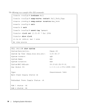
The following is an example of the CLI commands: Console (config)# hostname dell Console (config)# snmp-server contact Dell_Tech_Supp Console (config)# snmp-server location New_York Console (config)# exit Console # exit Console (config)# asset-tag 1qwepot Console> ... source DELL Switch# show system System Description: System Up Time (days,hour:min:sec): System Contact: System Name: System Location: System MAC Address: Sys Object ID: Kenan 24 0,00:04:17 spk RS1 R&D 00:10:b5:f4:00:01 1.3.6.1.4.1.674.10895.3000 Type: Main Power Supply Status ok PowerConnect 5400 Redundant Power Supply Status:...
The following is an example of the CLI commands: Console (config)# hostname dell Console (config)# snmp-server contact Dell_Tech_Supp Console (config)# snmp-server location New_York Console (config)# exit Console # exit Console (config)# asset-tag 1qwepot Console> ... source DELL Switch# show system System Description: System Up Time (days,hour:min:sec): System Contact: System Name: System Location: System MAC Address: Sys Object ID: Kenan 24 0,00:04:17 spk RS1 R&D 00:10:b5:f4:00:01 1.3.6.1.4.1.674.10895.3000 Type: Main Power Supply Status ok PowerConnect 5400 Redundant Power Supply Status:...

User's Guide
Page 77
... not present for the specified unit. • Fan - System Health • Power Supply Status - The main power supply state. The device fan status. Configuring System Information 77 Viewing System Health Information The System Health page shows physical ...unit. - - The fans are not operating normally for the specified unit. - The fans are not present for the specified unit - - The power supply is not operating normally for the specified unit. - Not Present - Not Present - System Health CLI Commands CLI Command show system Description Displays system ...
... not present for the specified unit. • Fan - System Health • Power Supply Status - The main power supply state. The device fan status. Configuring System Information 77 Viewing System Health Information The System Health page shows physical ...unit. - - The fans are not operating normally for the specified unit. - The fans are not present for the specified unit - - The power supply is not operating normally for the specified unit. - Not Present - Not Present - System Health CLI Commands CLI Command show system Description Displays system ...
User's Guide
Page 78
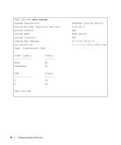
DELL Switch# show system System Description: System Up Time (days,hour:min:sec): System Contact: System Name: System Location: System MAC Address: Sys Object ID: Type: PowerConnect 5400 Power Supply Main Redundant Status -------OK OK FAN 1 2 Status -------OK OK DELL Switch# Ethernet Routing Switch 0,00:04:17 spk DELL Switch R&D 00:10:b5:f4:00:01 1.3.6.1.4.1.674.10895.3000 78 Configuring System Information
DELL Switch# show system System Description: System Up Time (days,hour:min:sec): System Contact: System Name: System Location: System MAC Address: Sys Object ID: Type: PowerConnect 5400 Power Supply Main Redundant Status -------OK OK FAN 1 2 Status -------OK OK DELL Switch# Ethernet Routing Switch 0,00:04:17 spk DELL Switch R&D 00:10:b5:f4:00:01 1.3.6.1.4.1.674.10895.3000 78 Configuring System Information
User's Guide
Page 443
... P Package Contents, 32 Package contents, 32 Passwords, 62, 171 PDU, 437 PING, 438 Port, 26 Port aggregation, 351 Port LEDs, 27 Ports, 60, 278, 405 Power supplies, 29 PPP, 438 Profiles, 147 Protocol, 337 PVID, 331, 334 Q QinQ, 323 QoS, 411, 414, 416, 438 Quality of Service, 411, 438 Queue, 419 R RADIUS...
... P Package Contents, 32 Package contents, 32 Passwords, 62, 171 PDU, 437 PING, 438 Port, 26 Port aggregation, 351 Port LEDs, 27 Ports, 60, 278, 405 Power supplies, 29 PPP, 438 Profiles, 147 Protocol, 337 PVID, 331, 334 Q QinQ, 323 QoS, 411, 414, 416, 438 Quality of Service, 411, 438 Queue, 419 R RADIUS...

Getting Started Guide
Page 5
Contents 1 Installation Overview 5 Site Preparation 5 Site Requirements 5 Unpacking 6 Package Contents 6 Unpacking the Device 6 2 Mounting the Device Overview 7 Device Rack Installation 7 Installing on a Flat Surface 8 Installing on a Wall 8 Connecting a Device to a Power Supply 9 3 Starting and Configuring the Device Connecting the Terminal to the Device 11 Booting the Switch 13 Initial Configuration 13 Contents 3
Contents 1 Installation Overview 5 Site Preparation 5 Site Requirements 5 Unpacking 6 Package Contents 6 Unpacking the Device 6 2 Mounting the Device Overview 7 Device Rack Installation 7 Installing on a Flat Surface 8 Installing on a Wall 8 Connecting a Device to a Power Supply 9 3 Starting and Configuring the Device Connecting the Terminal to the Device 11 Booting the Switch 13 Initial Configuration 13 Contents 3
Getting Started Guide
Page 7
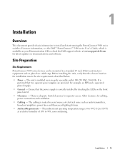
...is 0 to 45ºC (32 to 113ºF) at www.support.dell.com for operator access. The cabling is preferred that two separate power supplies are lit. • Clearance - Site Preparation Site Requirements PowerConnect 5400 series devices can be mounted in a standard 19 inch (48.26... centimeters) equipment rack or placed on your Documentation CD or check the Dell support website at a relative...
...is 0 to 45ºC (32 to 113ºF) at www.support.dell.com for operator access. The cabling is preferred that two separate power supplies are lit. • Clearance - Site Preparation Site Requirements PowerConnect 5400 series devices can be mounted in a standard 19 inch (48.26... centimeters) equipment rack or placed on your Documentation CD or check the Dell support website at a relative...

Getting Started Guide
Page 9
...line up to the mounting holes on the rack mounting bracket. The following mounting instructions apply to the PowerConnect 5400 series switches. Connecting a Redundant Power Supply (RPS) is optional, but is located on the back panel. Figure 2-1. Bracket Installation for the ...device is positioned on the device back panel. The power connectors for Rack Mounting Mounting the Device 7 The RPS connector is recommended....
...line up to the mounting holes on the rack mounting bracket. The following mounting instructions apply to the PowerConnect 5400 series switches. Connecting a Redundant Power Supply (RPS) is optional, but is located on the back panel. Figure 2-1. Bracket Installation for the ...device is positioned on the device back panel. The power connectors for Rack Mounting Mounting the Device 7 The RPS connector is recommended....

Getting Started Guide
Page 11
Mounting the Device 9 Connect the device to a grounded AC outlet at this time. Bracket Installation for Wall Mounting Connecting a Device to a Power Supply 1 Using the supplied AC power cable, connect the power cable to the AC connector located on the back panel. 2 Do not connect the power cable to a power source in the steps detailed in Starting and Configuring the Device. Figure 2-2.
Mounting the Device 9 Connect the device to a grounded AC outlet at this time. Bracket Installation for Wall Mounting Connecting a Device to a Power Supply 1 Using the supplied AC power cable, connect the power cable to the AC connector located on the back panel. 2 Do not connect the power cable to a power source in the steps detailed in Starting and Configuring the Device. Figure 2-2.


