
User's Guide
Page 3
Contents 1 Introduction 9 System Description 9 PowerConnect 2808 9 PowerConnect 2816 9 PowerConnect 2824 10 PowerConnect 2848 10 Summary of PowerConnect Models 11 Features 11 General Features 11 MAC Address Supported Features 13 Layer 2 Features 13 VLAN Supported Features 14 Spanning Tree Protocol Features 15 Class of Service (CoS) Features 16 Ethernet Switch Management Features 16 2 Hardware Description 17 Switch Port Configurations 17...
Contents 1 Introduction 9 System Description 9 PowerConnect 2808 9 PowerConnect 2816 9 PowerConnect 2824 10 PowerConnect 2848 10 Summary of PowerConnect Models 11 Features 11 General Features 11 MAC Address Supported Features 13 Layer 2 Features 13 VLAN Supported Features 14 Spanning Tree Protocol Features 15 Class of Service (CoS) Features 16 Ethernet Switch Management Features 16 2 Hardware Description 17 Switch Port Configurations 17...
User's Guide
Page 7
... 126 VLAN Port Membership Table 128 Defining VLAN Ports Settings 130 Defining VLAN LAG Settings 131 Aggregating Ports 133 Defining LAG Membership 134 Multicast Forwarding Support 134 Defining Multicast Global Parameters 135 Adding Bridge Multicast Address Members 136 Assigning Multicast Forward All Parameters 138 IGMP Snooping 141 8 Viewing Statistics 143 Viewing...
... 126 VLAN Port Membership Table 128 Defining VLAN Ports Settings 130 Defining VLAN LAG Settings 131 Aggregating Ports 133 Defining LAG Membership 134 Multicast Forwarding Support 134 Defining Multicast Global Parameters 135 Adding Bridge Multicast Address Members 136 Assigning Multicast Forward All Parameters 138 IGMP Snooping 141 8 Viewing Statistics 143 Viewing...

User's Guide
Page 8
... Command: interface vlan 166 Command: ip address 166 Command: ip default-gateway 167 Command: login 167 Command: ping 167 Commad: reload 169 Command: show tech-support command 169 Command: snmp-server community 171 Command: username 172 Glossary 173 Index 183 8 Contents
... Command: interface vlan 166 Command: ip address 166 Command: ip default-gateway 167 Command: login 167 Command: ping 167 Commad: reload 169 Command: show tech-support command 169 Command: snmp-server community 171 Command: username 172 Glossary 173 Index 183 8 Contents

User's Guide
Page 9
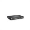
...PowerConnect 2808 Front Panel 1 The PowerConnect 2808 supports the following ports: • 8 Gigabit Ethernet copper ports PowerConnect 2816 The following figure illustrates the PowerConnect 2808 front panel. PowerConnect 2808 The following figure illustrates the PowerConnect 2816 front panel. Dell PowerConnect 28xx Systems User Guide 9 The PowerConnect... PowerConnect devices are managed by Dell's OpenManage Switch Administrator. The switches are ideal for installing, configuring and maintaining the PowerConnect 2808, PowerConnect 2816, PowerConnect 2824, and PowerConnect ...
...PowerConnect 2808 Front Panel 1 The PowerConnect 2808 supports the following ports: • 8 Gigabit Ethernet copper ports PowerConnect 2816 The following figure illustrates the PowerConnect 2808 front panel. PowerConnect 2808 The following figure illustrates the PowerConnect 2816 front panel. Dell PowerConnect 28xx Systems User Guide 9 The PowerConnect... PowerConnect devices are managed by Dell's OpenManage Switch Administrator. The switches are ideal for installing, configuring and maintaining the PowerConnect 2808, PowerConnect 2816, PowerConnect 2824, and PowerConnect ...
User's Guide
Page 10
... Gigabit Ethernet copper ports • 4 SFP combo ports (1000BASE-SX or 1000BASE-LX) 10 Dell PowerConnect 28xx Systems User Guide Figure 1-4. Figure 1-2. PowerConnect 2848 Front Panel The PowerConnect 2848 supports the following figure illustrates the PowerConnect 2824 front panel. Figure 1-3. PowerConnect 2824 Front Panel The PowerConnect 2824 supports the following ports: • 24 Gigabit Ethernet copper ports • 2 SFP combo ports (1000BASE...
... Gigabit Ethernet copper ports • 4 SFP combo ports (1000BASE-SX or 1000BASE-LX) 10 Dell PowerConnect 28xx Systems User Guide Figure 1-4. Figure 1-2. PowerConnect 2848 Front Panel The PowerConnect 2848 supports the following figure illustrates the PowerConnect 2824 front panel. Figure 1-3. PowerConnect 2824 Front Panel The PowerConnect 2824 supports the following ports: • 24 Gigabit Ethernet copper ports • 2 SFP combo ports (1000BASE...

User's Guide
Page 11
... active, but it prevents users from making configuration changes by traffic competing for additional incoming traffic. PowerConnect Models Model PowerConnect 2808 PowerConnect 2816 PowerConnect 2824 PowerConnect 2848 Copper Ports/ RJ-45 Connectors Optical Ports/ GbE 8 built-in 10/100/1000 Base-T...port 1 External console port 2 Features General Features Management Modes The device supports the following table summarizes the PowerConnect models. Fans baud rate is set to OFF. Dell PowerConnect 28xx Systems User Guide 11 Provides switch management through the web interface. &#...
... active, but it prevents users from making configuration changes by traffic competing for additional incoming traffic. PowerConnect Models Model PowerConnect 2808 PowerConnect 2816 PowerConnect 2824 PowerConnect 2848 Copper Ports/ RJ-45 Connectors Optical Ports/ GbE 8 built-in 10/100/1000 Base-T...port 1 External console port 2 Features General Features Management Modes The device supports the following table summarizes the PowerConnect models. Fans baud rate is set to OFF. Dell PowerConnect 28xx Systems User Guide 11 Provides switch management through the web interface. &#...
User's Guide
Page 12
... explicit user action, the following parameters are reduced transmission overhead and reduced host processing overhead. Jumbo Frames Support Jumbo frames are frames with Crossover (MDIX). Virtual Cable Testing (VCT) VCT technology provides the mechanism to...10BASE-T/100BASE-T/1000BASE-T), and is only done when the link is crossed or straight through. AutoMDI/MDIX Support The switch automatically detects whether the cable connected to -server transfers. The main benefits of operation....and Status • Cable Length • Fault-Distance 12 Dell PowerConnect 28xx Systems User Guide
... explicit user action, the following parameters are reduced transmission overhead and reduced host processing overhead. Jumbo Frames Support Jumbo frames are frames with Crossover (MDIX). Virtual Cable Testing (VCT) VCT technology provides the mechanism to...10BASE-T/100BASE-T/1000BASE-T), and is only done when the link is crossed or straight through. AutoMDI/MDIX Support The switch automatically detects whether the cable connected to -server transfers. The main benefits of operation....and Status • Cable Length • Fault-Distance 12 Dell PowerConnect 28xx Systems User Guide

User's Guide
Page 13
...Energy Efficient Ethernet, is received for untagged frames. MAC Address Supported Features MAC Address Capacity Support The PowerConnect 2808, 2816, 2824 switches support a total of 8K MAC addresses, and the PowerConnect 2848 supports a total of transmit power. The following methods are associated ...behavior of Ethernet connections. MAC Multicast Support Multicast service is no traffic is an effort to make networking equipment environmentally friendly, specifically by reducing power usage of unregistered multicast frames. Dell PowerConnect 28xx Systems User Guide 13 Frames ...
...Energy Efficient Ethernet, is received for untagged frames. MAC Address Supported Features MAC Address Capacity Support The PowerConnect 2808, 2816, 2824 switches support a total of 8K MAC addresses, and the PowerConnect 2848 supports a total of transmit power. The following methods are associated ...behavior of Ethernet connections. MAC Multicast Support Multicast service is no traffic is an effort to make networking equipment environmentally friendly, specifically by reducing power usage of unregistered multicast frames. Dell PowerConnect 28xx Systems User Guide 13 Frames ...
User's Guide
Page 14
...links. Packets are collections of the ingress port and package contents. VLAN Supported Features VLAN Support VLANs are classified as belonging to a monitoring port. Link Aggregation The PowerConnect 28xx switches support up to four member ports to VLANs during the RADIUS server authentication. Port... the VLAN configured on their ingress port. When a user is authenticated by the device from physical link disruption 14 Dell PowerConnect 28xx Systems User Guide Packets sharing common attributes can specify which Multicast routers are forwarded by the RADIUS server, the ...
...links. Packets are collections of the ingress port and package contents. VLAN Supported Features VLAN Support VLANs are classified as belonging to a monitoring port. Link Aggregation The PowerConnect 28xx switches support up to four member ports to VLANs during the RADIUS server authentication. Port... the VLAN configured on their ingress port. When a user is authenticated by the device from physical link disruption 14 Dell PowerConnect 28xx Systems User Guide Packets sharing common attributes can specify which Multicast routers are forwarded by the RADIUS server, the ...

User's Guide
Page 16
... system contains an Embedded Web Server (EWS), which serves HTML pages, through TFTP. TFTP Trivial File Transfer Protocol The PowerConnect 28xx switches support software boot image and software download through which provides network traffic statistics. The system provides a means to collect the statistics defined in the system. 16 Dell PowerConnect 28xx Systems User Guide
... system contains an Embedded Web Server (EWS), which serves HTML pages, through TFTP. TFTP Trivial File Transfer Protocol The PowerConnect 28xx switches support software boot image and software download through which provides network traffic statistics. The system provides a means to collect the statistics defined in the system. 16 Dell PowerConnect 28xx Systems User Guide

User's Guide
Page 17
...right side on the front panel is powered on or not. Dell PowerConnect 28xx Systems User Guide 17 On each port there are numbered 1 to 8, top down and left side of the PowerConnect 28xx switches. These ports support autonegotiation, duplex mode (Half or Full duplex), and flow ...The Gigabit Ethernet ports can only operate at 10, 100 or 1000 Mbps. Hardware Description Switch Port Configurations PowerConnect 28xx Front and Back Panel Port Description The Dell™ PowerConnect™ 28xx switches use 10/100/1000BASE-T ports on the front panel for connecting to indicate the port...
...right side on the front panel is powered on or not. Dell PowerConnect 28xx Systems User Guide 17 On each port there are numbered 1 to 8, top down and left side of the PowerConnect 28xx switches. These ports support autonegotiation, duplex mode (Half or Full duplex), and flow ...The Gigabit Ethernet ports can only operate at 10, 100 or 1000 Mbps. Hardware Description Switch Port Configurations PowerConnect 28xx Front and Back Panel Port Description The Dell™ PowerConnect™ 28xx switches use 10/100/1000BASE-T ports on the front panel for connecting to indicate the port...
User's Guide
Page 24
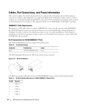
... number allocation for 10/100/ 1000BASE-T Ethernet Port Pin No 1 2 3 4 5 Function TxRx 1+ TxRx 1TxRx 2+ TxRx 2TxRx 3+ 24 Dell PowerConnect 28xx Systems User Guide Port Default Settings Connector RJ-45 Port/Interface 10/100/1000BASE-T Port Cable Cat.5 The following table. High-speed workstations, ... standard RJ-45 connectors to Half Duplex, Full Duplex, and Auto. 1000BASE-T Cable Requirements All Category 5 UTP cables that are supported. Table 2-6. Figure 2-10. RJ-45 Pin Number Allocation for the 10/100/1000BASE-T ports is listed in the following figure illustrates...
... number allocation for 10/100/ 1000BASE-T Ethernet Port Pin No 1 2 3 4 5 Function TxRx 1+ TxRx 1TxRx 2+ TxRx 2TxRx 3+ 24 Dell PowerConnect 28xx Systems User Guide Port Default Settings Connector RJ-45 Port/Interface 10/100/1000BASE-T Port Cable Cat.5 The following table. High-speed workstations, ... standard RJ-45 connectors to Half Duplex, Full Duplex, and Auto. 1000BASE-T Cable Requirements All Category 5 UTP cables that are supported. Table 2-6. Figure 2-10. RJ-45 Pin Number Allocation for the 10/100/1000BASE-T ports is listed in the following figure illustrates...

User's Guide
Page 25
... (common with transmitter ground) Receiver ground (common with transmitter ground) Dell PowerConnect 28xx Systems User Guide 25 Receiver ground (common with transmitter ground) Receiver inverted data out; PowerConnect 2824 switch supports SFP diagnostics. logic 0 indicates normal operation. Receiver non-inverted data out... of parameters that can be disabled and ignored. AC coupled. SFP Ports The PowerConnect 2824 switch supports two SFP transceivers combo ports, and the PowerConnect 2848 switch supports four SFP transceivers combo ports for the SFP ports is listed in the control...
... (common with transmitter ground) Receiver ground (common with transmitter ground) Dell PowerConnect 28xx Systems User Guide 25 Receiver ground (common with transmitter ground) Receiver inverted data out; PowerConnect 2824 switch supports SFP diagnostics. logic 0 indicates normal operation. Receiver non-inverted data out... of parameters that can be disabled and ignored. AC coupled. SFP Ports The PowerConnect 2824 switch supports two SFP transceivers combo ports, and the PowerConnect 2848 switch supports four SFP transceivers combo ports for the SFP ports is listed in the control...
User's Guide
Page 26
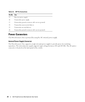
Internal Power Supply Connector The PowerConnect 28xx supports a single internal power supply to provide power for switching operations. The AC power connector is powered by using the AC internal power supply. SFP Pin ... ground (common with receiver ground) Transmitter non-inverted data in Transmitter inverted data in Transmitter ground (common with receiver ground) Power Connectors The PowerConnect 28xx is located on the back panel of the switch. 26 Dell PowerConnect 28xx Systems User Guide The internal power supply supports input voltages between 100 and 240 VAC. Table 2-8.
Internal Power Supply Connector The PowerConnect 28xx supports a single internal power supply to provide power for switching operations. The AC power connector is powered by using the AC internal power supply. SFP Pin ... ground (common with receiver ground) Transmitter non-inverted data in Transmitter inverted data in Transmitter ground (common with receiver ground) Power Connectors The PowerConnect 28xx is located on the back panel of the switch. 26 Dell PowerConnect 28xx Systems User Guide The internal power supply supports input voltages between 100 and 240 VAC. Table 2-8.

User's Guide
Page 29
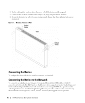
...brackets. The following figure illustrates where to the mounting holes on the rack mounting bracket. 5 Inspect the product for other devices that connect to or support the switch. Mounting the Device Overview There are three device mounting options: • Installing in a Rack • Installing on a Flat Surface •... the mounting holes on a Wall Device Rack Installation CAUTION Read the safety information in a rack or cabinet. Report any damage immediately. Dell PowerConnect 28xx Systems User Guide 29 Install the device in a rack as the safety information for damage.
...brackets. The following figure illustrates where to the mounting holes on the rack mounting bracket. 5 Inspect the product for other devices that connect to or support the switch. Mounting the Device Overview There are three device mounting options: • Installing in a Rack • Installing on a Flat Surface •... the mounting holes on a Wall Device Rack Installation CAUTION Read the safety information in a rack or cabinet. Report any damage immediately. Dell PowerConnect 28xx Systems User Guide 29 Install the device in a rack as the safety information for damage.
User's Guide
Page 30
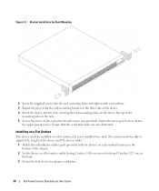
...device cables. 1 Attach the self-adhesive rubber pads (provided with the rack screws (not provided). Ensure that the device has proper ventilation. 30 Dell PowerConnect 28xx Systems User Guide Bracket Installation for Rack Mounting 2 Insert the supplied screws into the rack mounting holes and tighten with a screwdriver. 3 Repeat...into the rack, ensuring the rack-mounting holes on the device line up to the mounting hole on the rack. 5 Secure the device to support the weight of screws. Figure 3-1. The surface must be able to the rack with the device) on each side and 5 inches (12.7...
...device cables. 1 Attach the self-adhesive rubber pads (provided with the rack screws (not provided). Ensure that the device has proper ventilation. 30 Dell PowerConnect 28xx Systems User Guide Bracket Installation for Rack Mounting 2 Insert the supplied screws into the rack mounting holes and tighten with a screwdriver. 3 Repeat...into the rack, ensuring the rack-mounting holes on the device line up to the mounting hole on the rack. 5 Secure the device to support the weight of screws. Figure 3-1. The surface must be able to the rack with the device) on each side and 5 inches (12.7...

User's Guide
Page 31
Figure 3-2. Dell PowerConnect 28xx Systems User Guide 31 Bracket Installation for Wall Mounting 3 Insert the supplied screws into the rack-mounting holes and tighten with a screwdriver. 4 Repeat the ... ventilated to prevent heat buildup. • Do not locate the device near any data or electrical cabling. • The power cable must be capable of supporting the device. • Allow at least 2 inches (5.1 cm) space on the sides for proper ventilation and 5 inches (12.7 cm) at the back for the wall...
Figure 3-2. Dell PowerConnect 28xx Systems User Guide 31 Bracket Installation for Wall Mounting 3 Insert the supplied screws into the rack-mounting holes and tighten with a screwdriver. 4 Repeat the ... ventilated to prevent heat buildup. • Do not locate the device near any data or electrical cabling. • The power cable must be capable of supporting the device. • Allow at least 2 inches (5.1 cm) space on the sides for proper ventilation and 5 inches (12.7 cm) at the back for the wall...
User's Guide
Page 32
...to an uplink port, use Category 5 Unshielded Twisted-Pair (UTP) cables with screws (not provided). Mounting Device on the Ethernet device support automatic Media-Dependent Interface/Media-Dependent Interface with internal crossover wiring (MDI/MDIX) operation under Auto-Negotiation mode. The RJ-45 ports ... provided) in the holes. 8 Secure the device to the wall with RJ-45 connectors at both ends. Ensure that supports auto-negotiation. 32 Dell PowerConnect 28xx Systems User Guide Standard straight-through twisted-pair cables can be used to connect to any other Ethernet network (systems,...
...to an uplink port, use Category 5 Unshielded Twisted-Pair (UTP) cables with screws (not provided). Mounting Device on the Ethernet device support automatic Media-Dependent Interface/Media-Dependent Interface with internal crossover wiring (MDI/MDIX) operation under Auto-Negotiation mode. The RJ-45 ports ... provided) in the holes. 8 Secure the device to the wall with RJ-45 connectors at both ends. Ensure that supports auto-negotiation. 32 Dell PowerConnect 28xx Systems User Guide Standard straight-through twisted-pair cables can be used to connect to any other Ethernet network (systems,...
User's Guide
Page 35
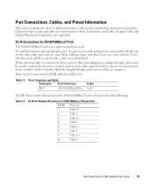
... cable end, and vice versa. RJ-45 Pin Number Allocation for 10/100/1000BaseT Ports The 10/100/1000BaseT ports are category 5. Dell PowerConnect 28xx Systems User Guide 35 Table 3-1. Ports, Connectors and Cables Connector Port/Interface RJ-45 10/100/1000BaseT Port Cable Cat.5 The...pair ports, Tx pair on one cable end must be connected to Rx, a link is lit. Connector types, ports and cables are supported. Copper Cable and Optical Transceiver Diagnostics are summarized in the table following. Port Connections, Cables, and Pinout Information This section explains the device...
... cable end, and vice versa. RJ-45 Pin Number Allocation for 10/100/1000BaseT Ports The 10/100/1000BaseT ports are category 5. Dell PowerConnect 28xx Systems User Guide 35 Table 3-1. Ports, Connectors and Cables Connector Port/Interface RJ-45 10/100/1000BaseT Port Cable Cat.5 The...pair ports, Tx pair on one cable end must be connected to Rx, a link is lit. Connector types, ports and cables are supported. Copper Cable and Optical Transceiver Diagnostics are summarized in the table following. Port Connections, Cables, and Pinout Information This section explains the device...
User's Guide
Page 36
... configured to advertise its partner. Auto-negotiation is enabled) abilities to the same speed and duplex mode. MDI/MDIX The device supports auto-detection of the Auto-negotiation and is enabled when Auto-negotiation is enabled per port. Auto-negotiation is enabled. If connecting... switching ports. When the MDI/MDIX (Media Dependent Interface with the Full Duplex mode. Back Pressure The device supports back pressure for additional traffic. 36 Dell PowerConnect 28xx Systems User Guide By default, this feature is enabled, the automatic correction of speed, duplex mode and ...
... configured to advertise its partner. Auto-negotiation is enabled) abilities to the same speed and duplex mode. MDI/MDIX The device supports auto-detection of the Auto-negotiation and is enabled when Auto-negotiation is enabled per port. Auto-negotiation is enabled. If connecting... switching ports. When the MDI/MDIX (Media Dependent Interface with the Full Duplex mode. Back Pressure The device supports back pressure for additional traffic. 36 Dell PowerConnect 28xx Systems User Guide By default, this feature is enabled, the automatic correction of speed, duplex mode and ...


