
User's Guide
Page 3
Contents 1 Introduction 9 System Description 9 PowerConnect 2808 9 PowerConnect 2816 9 PowerConnect 2824 10 PowerConnect 2848 10 Summary of PowerConnect Models 11 Features 11 General Features 11 MAC Address Supported Features 13 Layer 2 Features 13 VLAN Supported Features 14 Spanning Tree ... Power LED 22 Managed Mode LED 22 Fan LED (2824/2848 only 22 Port LEDs 22 Managed Mode Button 23 Switch Ventilation Fan 23 Cables, Port Connections, and Pinout Information 24 1000BASE-T Cable Requirements 24 RJ-45 Connections for 10/100/1000BASE-T Ports 24 SFP Ports 25 Contents 3
Contents 1 Introduction 9 System Description 9 PowerConnect 2808 9 PowerConnect 2816 9 PowerConnect 2824 10 PowerConnect 2848 10 Summary of PowerConnect Models 11 Features 11 General Features 11 MAC Address Supported Features 13 Layer 2 Features 13 VLAN Supported Features 14 Spanning Tree ... Power LED 22 Managed Mode LED 22 Fan LED (2824/2848 only 22 Port LEDs 22 Managed Mode Button 23 Switch Ventilation Fan 23 Cables, Port Connections, and Pinout Information 24 1000BASE-T Cable Requirements 24 RJ-45 Connections for 10/100/1000BASE-T Ports 24 SFP Ports 25 Contents 3
User's Guide
Page 10
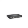
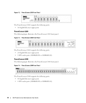
...: • 16 Gigabit Ethernet copper ports PowerConnect 2824 The following ports: • 48 Gigabit Ethernet copper ports • 4 SFP combo ports (1000BASE-SX or 1000BASE-LX) 10 Dell PowerConnect 28xx Systems User Guide Figure 1-4. PowerConnect 2848 Front Panel The PowerConnect 2848 supports the following figure illustrates the PowerConnect 2824 front panel. PowerConnect 2824 Front Panel The PowerConnect 2824 supports the following ports: •...
...: • 16 Gigabit Ethernet copper ports PowerConnect 2824 The following ports: • 48 Gigabit Ethernet copper ports • 4 SFP combo ports (1000BASE-SX or 1000BASE-LX) 10 Dell PowerConnect 28xx Systems User Guide Figure 1-4. PowerConnect 2848 Front Panel The PowerConnect 2848 supports the following figure illustrates the PowerConnect 2824 front panel. PowerConnect 2824 Front Panel The PowerConnect 2824 supports the following ports: •...

User's Guide
Page 11
... be changed. • Secure Mode - Dell PowerConnect 28xx Systems User Guide 11 For more information about the management modes, see "Management Modes" on a per-port basis. PowerConnect Models Model PowerConnect 2808 PowerConnect 2816 PowerConnect 2824 PowerConnect 2848 Copper Ports/ RJ-45 Connectors Optical ...Ports/ GbE 8 built-in 10/100/1000 Base-T ports none 16 built-in 10/100/1000 Base-T ports none 24 built-in 10/100/1000 Base-T ports 2 SFP...
... be changed. • Secure Mode - Dell PowerConnect 28xx Systems User Guide 11 For more information about the management modes, see "Management Modes" on a per-port basis. PowerConnect Models Model PowerConnect 2808 PowerConnect 2816 PowerConnect 2824 PowerConnect 2848 Copper Ports/ RJ-45 Connectors Optical ...Ports/ GbE 8 built-in 10/100/1000 Base-T ports none 16 built-in 10/100/1000 Base-T ports none 24 built-in 10/100/1000 Base-T ports 2 SFP...

User's Guide
Page 19
PowerConnect 2824 Front Panel On the front panel there are 24 ports which indicates the Ethernet switch operational status and the management mode. NOTE: Only one of the two physical connections of a combo port can switch from the RJ-45 to the SFP (or vice versa) without resetting ...Modes" on or not. Port features and port controls are two SFP (Small Form-Factor Plugable) ports, designated as ports 23 and 24, for swappable optical transceiver, which offers high-speed 1000BASE-SX or 1000BASELX connection. Dell PowerConnect 28xx Systems User Guide 19 A Mode push-button, located on ...
PowerConnect 2824 Front Panel On the front panel there are 24 ports which indicates the Ethernet switch operational status and the management mode. NOTE: Only one of the two physical connections of a combo port can switch from the RJ-45 to the SFP (or vice versa) without resetting ...Modes" on or not. Port features and port controls are two SFP (Small Form-Factor Plugable) ports, designated as ports 23 and 24, for swappable optical transceiver, which offers high-speed 1000BASE-SX or 1000BASELX connection. Dell PowerConnect 28xx Systems User Guide 19 A Mode push-button, located on ...

User's Guide
Page 20
PowerConnect 2824 Back Panel Figure 2-7. PowerConnect 2848 Front Panel On the front panel there are numbered 1 to 48, top down and left to right. The four combo ports are logical ports with two physical connections: • An RJ-45 connection for Twisted Pair (TP) copper cabling. • An SFP port for ... of the front panel is powered on a combo port, and utilizes the information in all the control interfaces. A Mode push- 20 Dell PowerConnect 28xx Systems User Guide On each port, there are present, the SFP port will be the active port, whereas the RJ-45 port will be used .
PowerConnect 2824 Back Panel Figure 2-7. PowerConnect 2848 Front Panel On the front panel there are numbered 1 to 48, top down and left to right. The four combo ports are logical ports with two physical connections: • An RJ-45 connection for Twisted Pair (TP) copper cabling. • An SFP port for ... of the front panel is powered on a combo port, and utilizes the information in all the control interfaces. A Mode push- 20 Dell PowerConnect 28xx Systems User Guide On each port, there are present, the SFP port will be the active port, whereas the RJ-45 port will be used .

User's Guide
Page 23
... Duplex mode. The port is currently transmitting in the following table describes the SFP LED indications. Table 2-5. Switch Ventilation Fan The PowerConnect 2848 switch has three fans and the PowerConnect 2824 switch has one fan for resetting the device. The Mode button is established...45 LED indications are described in Full Duplex mode. Green Flashing Activity is established. Dell PowerConnect 28xx Systems User Guide 23 Off No link is established. Managed Mode Button The PowerConnect 28xx has a Mode push button on page 49. To transition between them, see...
... Duplex mode. The port is currently transmitting in the following table describes the SFP LED indications. Table 2-5. Switch Ventilation Fan The PowerConnect 2848 switch has three fans and the PowerConnect 2824 switch has one fan for resetting the device. The Mode button is established...45 LED indications are described in Full Duplex mode. Green Flashing Activity is established. Dell PowerConnect 28xx Systems User Guide 23 Off No link is established. Managed Mode Button The PowerConnect 28xx has a Mode push button on page 49. To transition between them, see...

User's Guide
Page 25
...with transmitter ground) Receiver ground (common with transmitter ground) Receiver ground (common with transmitter ground) Dell PowerConnect 28xx Systems User Guide 25 Receiver ground (common with transmitter ground) Receiver inverted data out; The...Rate select; SFP Ports The PowerConnect 2824 switch supports two SFP transceivers combo ports, and the PowerConnect 2848 switch supports four SFP transceivers combo ports for serial ID. PowerConnect 2824 switch supports SFP diagnostics. data line for the SFP ports is listed in the control interfaces. Table 2-8. SFP Pin Connections Pin...
...with transmitter ground) Receiver ground (common with transmitter ground) Receiver ground (common with transmitter ground) Dell PowerConnect 28xx Systems User Guide 25 Receiver ground (common with transmitter ground) Receiver inverted data out; The...Rate select; SFP Ports The PowerConnect 2824 switch supports two SFP transceivers combo ports, and the PowerConnect 2848 switch supports four SFP transceivers combo ports for serial ID. PowerConnect 2824 switch supports SFP diagnostics. data line for the SFP ports is listed in the control interfaces. Table 2-8. SFP Pin Connections Pin...
User's Guide
Page 26
... power supply supports input voltages between 100 and 240 VAC. Table 2-8. Internal Power Supply Connector The PowerConnect 28xx supports a single internal power supply to provide power for switching operations. SFP Pin Connections Pin No 15 16 17 18 19 20 Use Receiver power supply Transmitter power supply Transmitter...common with receiver ground) Transmitter non-inverted data in Transmitter inverted data in Transmitter ground (common with receiver ground) Power Connectors The PowerConnect 28xx is located on the back panel of the switch. 26 Dell PowerConnect 28xx Systems User Guide
... power supply supports input voltages between 100 and 240 VAC. Table 2-8. Internal Power Supply Connector The PowerConnect 28xx supports a single internal power supply to provide power for switching operations. SFP Pin Connections Pin No 15 16 17 18 19 20 Use Receiver power supply Transmitter power supply Transmitter...common with receiver ground) Transmitter non-inverted data in Transmitter inverted data in Transmitter ground (common with receiver ground) Power Connectors The PowerConnect 28xx is located on the back panel of the switch. 26 Dell PowerConnect 28xx Systems User Guide
User's Guide
Page 68
... transceiver temperature. • Voltage - Transmitter fault. Finisair transceivers do not support the transmitter fault diagnostic testing. • LOS - Fiber Optic analysis feature works only on SFPs that support the digital diagnostic standard SFF-4872. 68 Update with the following columns: • Temp - Measured TX output power in the cable. • Data...
... transceiver temperature. • Voltage - Transmitter fault. Finisair transceivers do not support the transmitter fault diagnostic testing. • LOS - Fiber Optic analysis feature works only on SFPs that support the digital diagnostic standard SFF-4872. 68 Update with the following columns: • Temp - Measured TX output power in the cable. • Data...
User's Guide
Page 174
.... Broadcast Storm An excessive amount of Service (CoS). CoS provides a method for tagging packets with two physical connections, including an RJ-45 connection and an SFP connection. 174 Glossary A file containing a device's configuration information. A overlapping transmission of a BootP server on a network. Combo Ports A single logical port with priority information. Enables a workstation...
.... Broadcast Storm An excessive amount of Service (CoS). CoS provides a method for tagging packets with two physical connections, including an RJ-45 connection and an SFP connection. 174 Glossary A file containing a device's configuration information. A overlapping transmission of a BootP server on a network. Combo Ports A single logical port with priority information. Enables a workstation...

