
User's Guide
Page 3
Contents 1 Introduction 9 System Description 9 PowerConnect 2808 9 PowerConnect 2816 9 PowerConnect 2824 10 PowerConnect 2848 10 Summary of PowerConnect Models 11 Features 11 General Features 11 MAC Address Supported Features 13 Layer 2 Features 13 VLAN Supported Features 14...Switch Management Features 16 2 Hardware Description 17 Switch Port Configurations 17 PowerConnect 28xx Front and Back Panel Port Description 17 Physical Dimensions 21 LED Definitions 21 Power LED 22 Managed Mode LED 22 Fan LED (2824/2848 only 22 Port LEDs 22 Managed Mode Button 23 Switch Ventilation...
Contents 1 Introduction 9 System Description 9 PowerConnect 2808 9 PowerConnect 2816 9 PowerConnect 2824 10 PowerConnect 2848 10 Summary of PowerConnect Models 11 Features 11 General Features 11 MAC Address Supported Features 13 Layer 2 Features 13 VLAN Supported Features 14...Switch Management Features 16 2 Hardware Description 17 Switch Port Configurations 17 PowerConnect 28xx Front and Back Panel Port Description 17 Physical Dimensions 21 LED Definitions 21 Power LED 22 Managed Mode LED 22 Fan LED (2824/2848 only 22 Port LEDs 22 Managed Mode Button 23 Switch Ventilation...

User's Guide
Page 11
Table 1-1. PowerConnect Models Model PowerConnect 2808 PowerConnect 2816 PowerConnect 2824 PowerConnect 2848 Copper Ports/ RJ-45 Connectors Optical Ports/... port where the HOL blocking prevention mechanism is set to OFF. The default status on page 49. Fans baud rate is unavailable for configuration. Head of Line Blocking Prevention Head of Line (HOL) blocking results... at the end of the queue. In this feature on the whole system. Dell PowerConnect 28xx Systems User Guide 11 Summary of PowerConnect Models The following modes: • Managed Mode - HOL blocking queues packets,...
Table 1-1. PowerConnect Models Model PowerConnect 2808 PowerConnect 2816 PowerConnect 2824 PowerConnect 2848 Copper Ports/ RJ-45 Connectors Optical Ports/... port where the HOL blocking prevention mechanism is set to OFF. The default status on page 49. Fans baud rate is unavailable for configuration. Head of Line Blocking Prevention Head of Line (HOL) blocking results... at the end of the queue. In this feature on the whole system. Dell PowerConnect 28xx Systems User Guide 11 Summary of PowerConnect Models The following modes: • Managed Mode - HOL blocking queues packets,...

User's Guide
Page 19
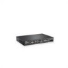
...: Only one time. The Fan LED indicates the device fan operations status, and the Power LED on the front panel indicates whether the device is powered on the front panel is the Managed Mode LED which offers high-speed 1000BASE-SX or 1000BASELX connection. PowerConnect 2824 Front Panel On the front panel...information in all the control interfaces. NOTE: The system can be disabled. A Mode push-button, located on the right side on or not. Dell PowerConnect 28xx Systems User Guide 19 The two combo ports are present, the SFP port will be the active port, whereas the RJ-45 port will...
...: Only one time. The Fan LED indicates the device fan operations status, and the Power LED on the front panel indicates whether the device is powered on the front panel is the Managed Mode LED which offers high-speed 1000BASE-SX or 1000BASELX connection. PowerConnect 2824 Front Panel On the front panel...information in all the control interfaces. NOTE: The system can be disabled. A Mode push-button, located on the right side on or not. Dell PowerConnect 28xx Systems User Guide 19 The two combo ports are present, the SFP port will be the active port, whereas the RJ-45 port will...

User's Guide
Page 20
...connection for Twisted Pair (TP) copper cabling. • An SFP port for fiber connection. The Fan LED indicates the device fan operations status, and the Power LED on or not. A Mode push- 20 Dell PowerConnect 28xx Systems User Guide NOTE: The system can be disabled. The four combo ports are four SFP...front panel indicates whether the device is the Managed Mode LED which indicates the Ethernet switch operational status and the management mode. Figure 2-6. PowerConnect 2824 Back Panel Figure 2-7. On the top right side of a combo port can switch from the RJ-45 to right...
...connection for Twisted Pair (TP) copper cabling. • An SFP port for fiber connection. The Fan LED indicates the device fan operations status, and the Power LED on or not. A Mode push- 20 Dell PowerConnect 28xx Systems User Guide NOTE: The system can be disabled. The four combo ports are four SFP...front panel indicates whether the device is the Managed Mode LED which indicates the Ethernet switch operational status and the management mode. Figure 2-6. PowerConnect 2824 Back Panel Figure 2-7. On the top right side of a combo port can switch from the RJ-45 to right...

User's Guide
Page 21
... device. Dell PowerConnect 28xx Systems User Guide 21 For more information about management modes and transitioning between management modes and to reset the device. Figure 2-8. Fans are provided on page 49. The back panel contains an AC Power Supply Interface. button, located on the right... • Height - 43.2 mm (1.7008 in.) • Width - 256 mm (10.079 in.) • Depth - 161.7 mm (6.366 in.) The PowerConnect 2816 and PowerConnect 2824 switches have the following physical dimensions: • Height - 43.2 mm (1.7008 in.) • Width - 330 mm (12.992 in.) • Depth - ...
... device. Dell PowerConnect 28xx Systems User Guide 21 For more information about management modes and transitioning between management modes and to reset the device. Figure 2-8. Fans are provided on page 49. The back panel contains an AC Power Supply Interface. button, located on the right... • Height - 43.2 mm (1.7008 in.) • Width - 256 mm (10.079 in.) • Depth - 161.7 mm (6.366 in.) The PowerConnect 2816 and PowerConnect 2824 switches have the following physical dimensions: • Height - 43.2 mm (1.7008 in.) • Width - 330 mm (12.992 in.) • Depth - ...

User's Guide
Page 22
... in Managed Mode. No valid image. Indicates Unmanaged mode or Secure mode. Fan LED Indications LED Color Green Solid Red Solid Description All fans are operating correctly. Managed Mode LED On the PowerConnect 28xx front panel there is a Power LED. Indicates the switch is in ... switch is indicated on page 49. The switch is a fan LED. The following figure illustrates the RJ-45 10/100/1000BASE-T LEDs. 22 Dell PowerConnect 28xx Systems User Guide Fan LED (2824/2848 only) On the PowerConnect 2824 and PowerConnect 2848 front panel there is not turned on . The following...
... in Managed Mode. No valid image. Indicates Unmanaged mode or Secure mode. Fan LED Indications LED Color Green Solid Red Solid Description All fans are operating correctly. Managed Mode LED On the PowerConnect 28xx front panel there is a Power LED. Indicates the switch is in ... switch is indicated on page 49. The switch is a fan LED. The following figure illustrates the RJ-45 10/100/1000BASE-T LEDs. 22 Dell PowerConnect 28xx Systems User Guide Fan LED (2824/2848 only) On the PowerConnect 2824 and PowerConnect 2848 front panel there is not turned on . The following...

User's Guide
Page 23
... Switch Ventilation Fan The PowerConnect 2848 switch has three fans and the PowerConnect 2824 switch has one fan for resetting the device. The port is transmitting or receiving data at either 10 or 100 Mbps. The Mode button is linked at 1000 Mbps. Dell PowerConnect 28xx Systems ...User Guide 23 The port is for changing between Managed Mode and Unmanaged (or Secure) Mode and for system ventilation. The PowerConnect 2808 and PowerConnect 2816 devices have no internal fans. Table 2-5. To transition between them...
... Switch Ventilation Fan The PowerConnect 2848 switch has three fans and the PowerConnect 2824 switch has one fan for resetting the device. The port is transmitting or receiving data at either 10 or 100 Mbps. The Mode button is linked at 1000 Mbps. Dell PowerConnect 28xx Systems ...User Guide 23 The port is for changing between Managed Mode and Unmanaged (or Secure) Mode and for system ventilation. The PowerConnect 2808 and PowerConnect 2816 devices have no internal fans. Table 2-5. To transition between them...

